Chapter 11 355
Assembly Replacement Procedures
RF Section E4446A, E4447A, E4448A
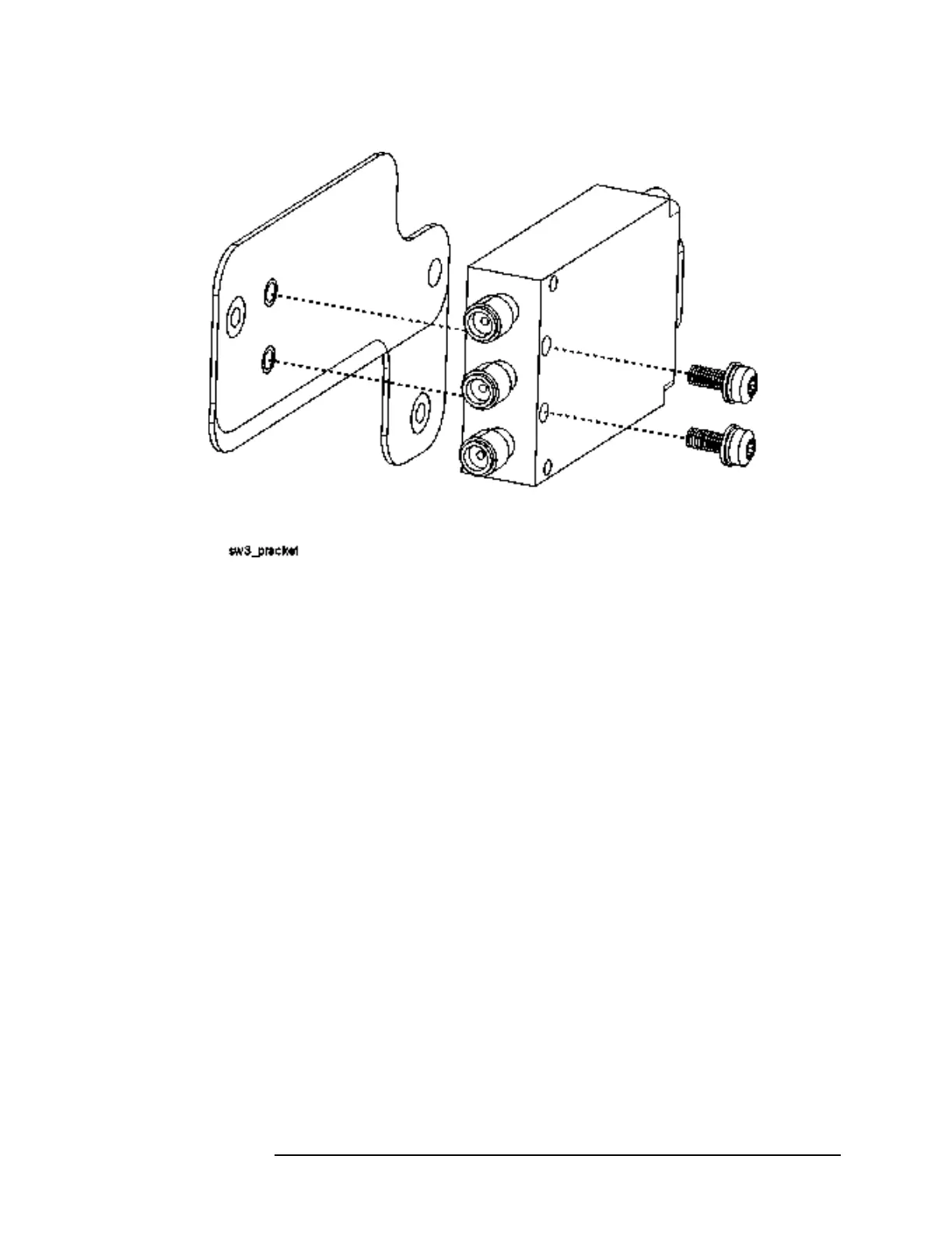
Figure 11-33 SW3 and Bracket
Replacement
1. Attach SW3 to the bracket using the two screws removed earlier.
Torque to 9 in-lbs.
2. Place the switch/bracket assembly into place on the main bracket.
Refer to Figure 11-31. Replace the two screws (4) that attach the
SW3 bracket to the main bracket. Torque to 9 inch-pounds.
3. Refer to Figure 11-32. Replace cables W89. W93, and W94. Torque to
9 in-lbs.
4. Replace ribbon cable W96.
5. Replace the front frame.
SW5 Switch
Removal
1. Drop the front frame. See page 314 for instructions.
2. Refer to Figure 11-31. Remove cables W99, W100, W105 and ribbon
cable W92.
3. Remove the three screws (2) that attach SW5 to the bracket. Lift
the switch/bracket assembly from the instrument.
4. Refer to Figure 11-34. To separate the switch from the bracket,
remove the three screws.
 Loading...


