358 Chapter 11
Assembly Replacement Procedures
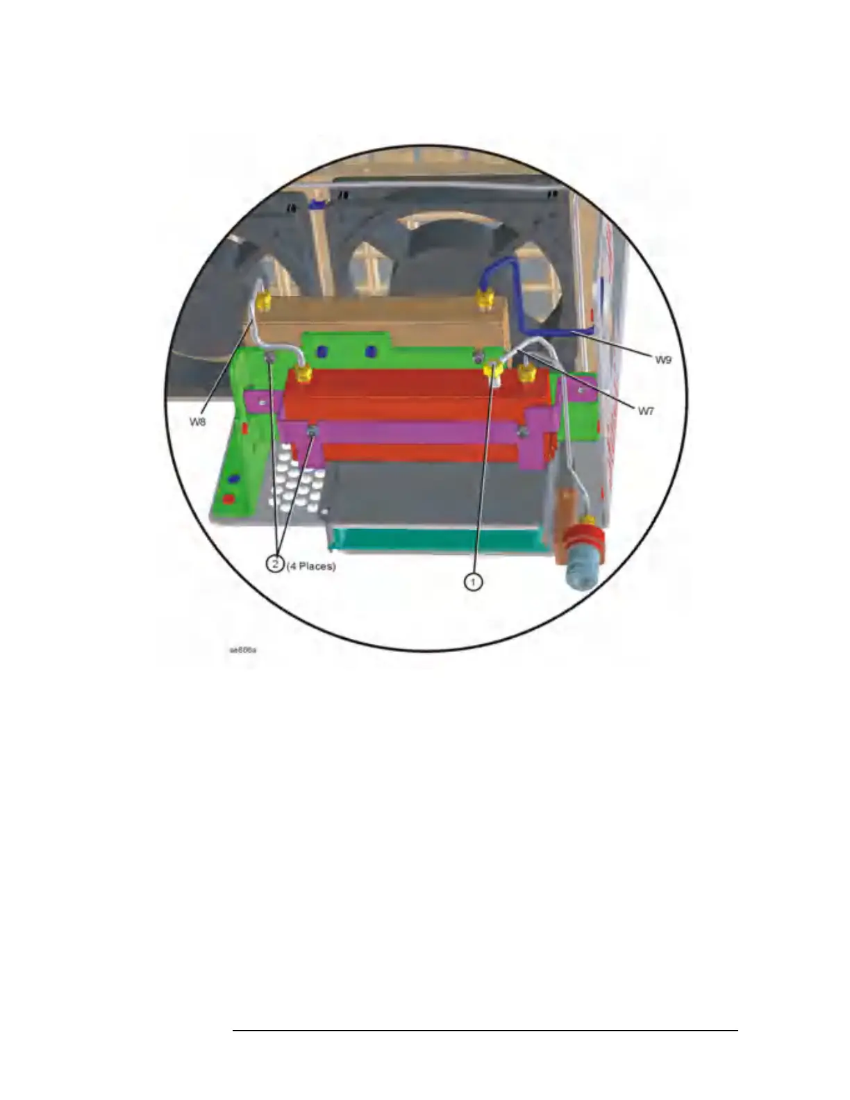
Attenuator Assembly E4440A, E4443A, E4445A
Figure 11-35 Attenuator Assembly Removal (E4440A, E4443A, E4445A)
Replacement
1. Position the attenuator assembly in the deck.
2. Using the T-10 driver, replace the 4 screws, but do not torque.
3. Replace the semi-rigid cables to the correct locations. Torque the
cables to 10 inch pounds.
4. Torque the screws to 9 inch pounds.
5. Replace the coaxial cable.
6. Dress the ribbon cables between the fan and deck and clip, and
reconnect to the correct locations.
7. Replace the front frame. Refer to the “Front Frame” section.
8. Replace the instrument top brace and outer case. Refer to the “Top
Brace” and the “Instrument Outer Case” replacement procedures.
 Loading...


