92 Chapter 4
Troubleshooting the RF Section (E4446A, E4447A, E4448A)
RF Section Description (E4446A, E4447A, E4448A)
• If the signal frequency is 3 Hz to 3 GHz, the SBTX switch routes the
signal through the 27 GHz low pass filter cable, bypassing the
tracking preselector and mixer. The 3 Hz to 3 GHz signal is applied
to FL1, the 3 GHz lowpass filter. If the instrument contains Option
1DS (preamplifier) or Option B7J, (digital demod hardware), the
signal also routes through them. The signal then enters the A20
Lowband assembly.
The A20 Lowband assembly contains both the first and second mixers.
The first mixer up-converts the RF signal to the 3.9214 GHz first IF.
The first IF signal leaves the Lowband assembly and routes through
the switch on the A30 FIFA assembly and then on to FL2, the
3.9214 GHz bandpass filter, before returning to the Lowband assembly.
The second mixer down-converts the first IF to the 321.4 MHz second
IF. The second IF is applied as one of the inputs to the A10 Third
Converter.
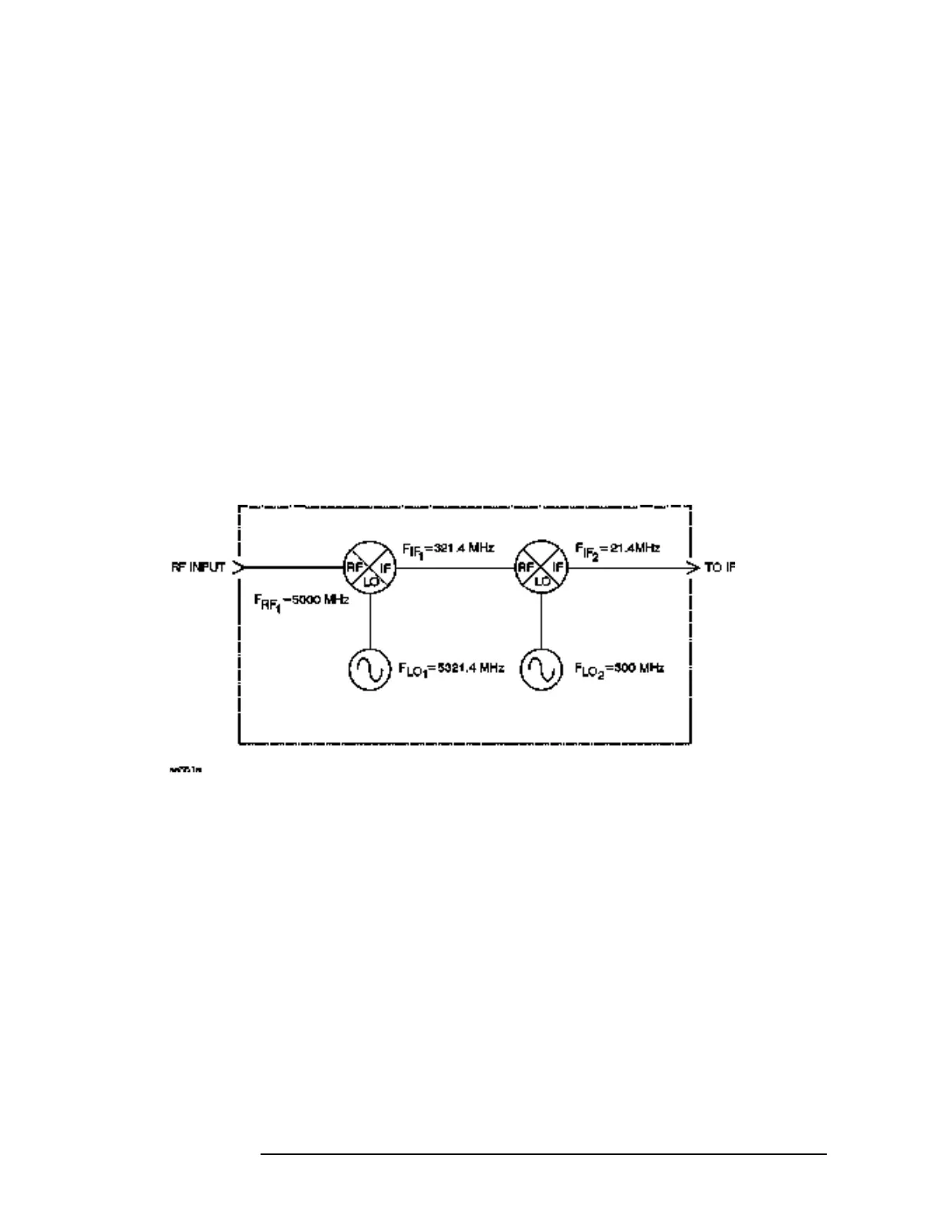
Figure 4-1 Example of Down Conversion
In the Third Converter, one of three possible 321.4 MHz IF signals is
selected. The signal at J1 is from the “highband” or microwave port of
the RYTHM converter. The signal at J2 is from the A20 Lowband
assembly. This can be either the 3 Hz to 3 GHz “lowband” input signal
that has been frequency shifted, or the 26.8 GHz to 50 GHz “millimeter
band” input signal that has been pre-filtered and down-converted in the
SBTX and then passed through the second converter. If Option AYZ is
present, J3 is the 321.4 MHz IF input from the external mixer.
The 321.4 MHz signal is fed to the system variable gain circuit that is
used to establish gain at 50 MHz as well as compensate for front end
frequency response as the instrument tunes across its frequency range.
The third converter down-converts the 321.4 MHz signal to 21.4 MHz.
 Loading...


