20 Installation Note E8362-90004
Replace the Bias Tees (Refer to Figure 12.)
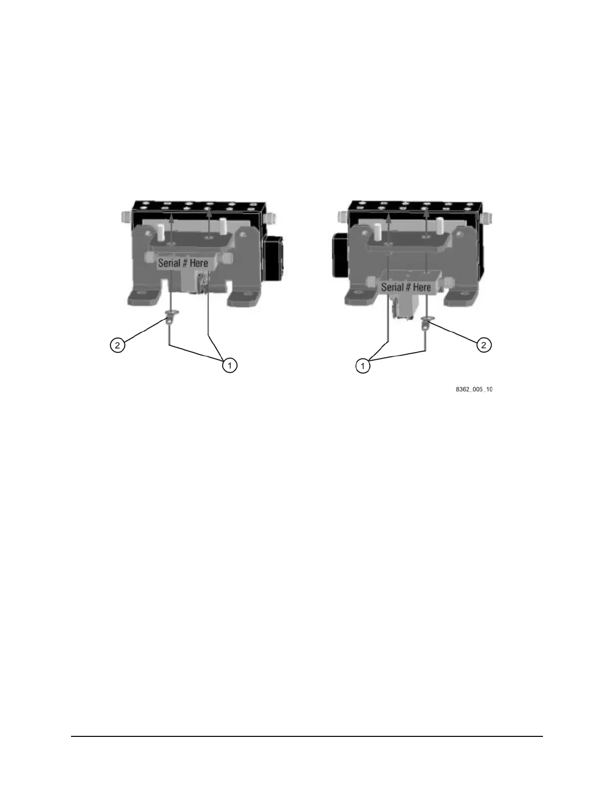
1. Remove the old bias tees from the bracket by removing two screws (item
①) from each.
Retain the screws for installing the new bias tees.
2. Install the new bias tees using the screws (item
①) removed from the old bias tees. Be sure
to install the ground lug (item
②) over the attachment screw as shown.
Figure 12 Bias Tees Replacement
Reinstall the Detector/Bias Tee/Attenuator Brackets (Refer to Figure 11.)
1. Place the brackets, with the attenuators and bias tees attached, into the analyzer as shown
in Figure 11.
2. Reinstall the three screws (item
④) in each bracket.
3. Reconnect the ribbon cables to the attenuators (item
①).
4. Reconnect the bias tee control cables to the A16 test set motherboard. The A38 cable
connects to J22 (P1 BIAS T) and the A39 cable connects to J25 (P2 BIAS T). Be sure to route
them under the cable clamp, (item
③).
5. Reconnect all RF cables to the attenuators (item
①) and bias tees (item ②).

 Loading...


