2-8 Service Guide E8364-90038
General Product Information PNA Series Microwave Network Analyzers
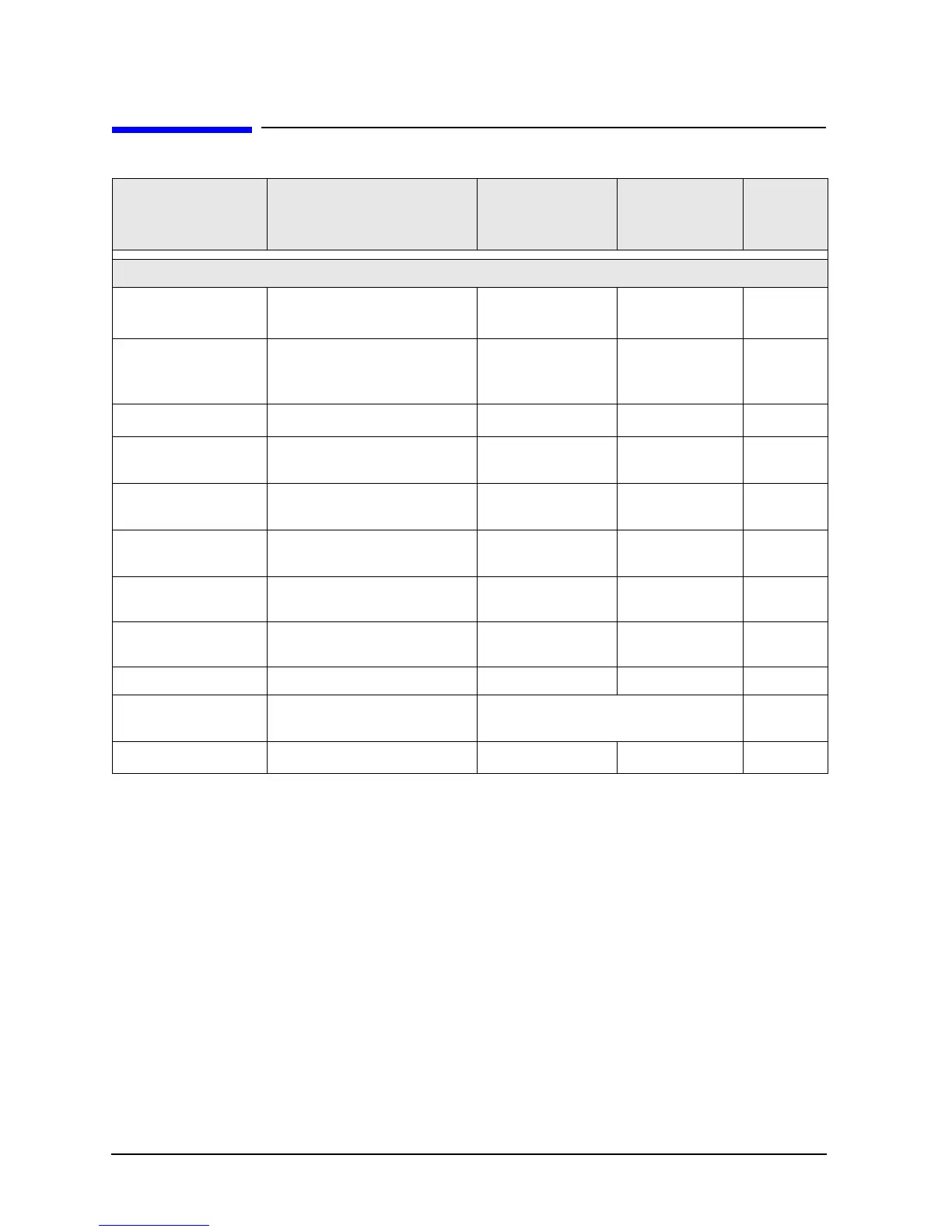
Required Service Test Equipment E8362C, E8363C, E8364C
Required Service Test Equipment
Equipment
a
a. Unless specified otherwise, equipment listed is required for all analyzer models.
Critical Specifications
Recommended
Model or Part
Number
Alternate Model
or Part Number
Use
b
b. P = Performance tests, A = Adjustments, T = Troubleshooting, V = System verification
Test Instruments and Software
Frequency counter
Freq: 10 MHz to 20 GHz
Accuracy : 0.5 ppm
53151A
Opt 001
None P, A,T
Spectrum analyzer
Min Freq: 1 MHz
Max Freq: > 4 GHz
Resolution BW: 300 Hz
8565E
856xE A,T
Power meter Accuracy: ±0.0068 dB E4418B/19B
E4418A/19A
c
c. If an accurate measurement of the dynamic accuracy specification is not required, the E4418A or E4419A can be used.
P, A,T
Power sensor
(All)
Freq: 10 MHz to 4.2 GHz
Range: –30 to +20 dBm
8482A
None
P, A,T
Power sensor
(E8362C)
Freq: 50 MHz to 20 GHz
Range: –30 to +20 dBm
E4413A
None
P, A,T
Power sensor
(E8363C, E8364C)
Freq: 50 MHz to 40 or 50 GHz
Range: –30 to +20 dBm
8487A
None
P, A,T
Dynamic accuracy
test set
None specified
Z5623A
Opt H01
None P
Compression
test set
None specified
Z5623A
Opt K01
None P
Digital voltmeter Resolution: 10 mV Any Any T
Printer N/A
Any printer with Microsoft Windows 2000
driver
P
Test soft ware
d
d. The recommended model or part number for all equipment listed with a “P” in the Use column is required for proper operation of
this test software.
N/A N7840A None
P