132 Chapter 2
Front-Panel Key Reference
Meas Setup
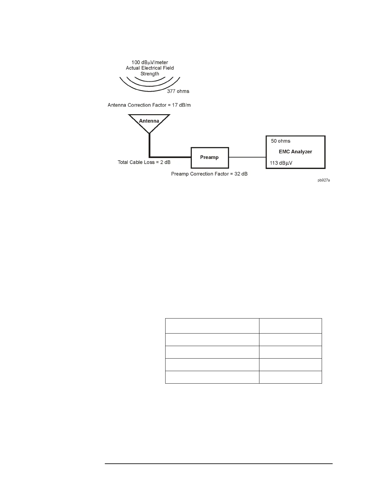
In order to transfer the measured signal amplitude to the true signal
level we must first “correct” for:
• The gain of the amplifier. Subtracting the amplitude gain correction
factor (32 dB) from 113 dBµV, will yield a level of 81 dBµV.
• The overall cable loss. Since the cable loss results in a measured
value lower then the actual value we must add the cable correction
factor (2 dB) to the 81 dBµV. This leaves us with 83 dBµV.
• The conversion loss between the intrinsic impedance of free space,
377 ohms, and the 50 ohm system the analyzer operates in. By
adding the antenna factor of 17 dBµV to 83 dBµV we find the true
signal field strength level of 100 dBµV.
Because of the way corrections are applied, the following convention is
used for indicating correction factors as positive or negative values.
The correction factor signs are only a convention. Although all
correction factors are handled the same algebraically, losses are
typically entered as positive corrections and gains are typically entered
as negative corrections.
Key Access:
Meas Setup, More
Correction Factor Sign
Antenna Factors Positive
Cable Factors Positive
Other Factors Positive
User Factors Negative
 Loading...


