Troubleshooting
Microprocessor
Assembly
(A3)
Troubleshooting
The
following
error
groups
pertain
to
the
microprocessor
assembly
.
Error Group Description
4=
Y
ABUS Errors
6
=
Y
7
=
Y
0.5
V/GHz
Output
Errors
Note
Prior
to
replacing
an
assembly
or
module
,
verify
that
the
power
supply
voltages
are
within
specication
at
the
power
connection
to
the
assembly or
module.
ABUS
Errors
Error
Group
Description
4
=
1
6
15
V
on
CPU
Assy
4
=
2
Digital
+5
V
on
the
CPU
Assy
4
=
4
Analog
+5
V
on
the
CPU
Assy
4
=
8
Digital
Ground
on
the
CPU
Assy
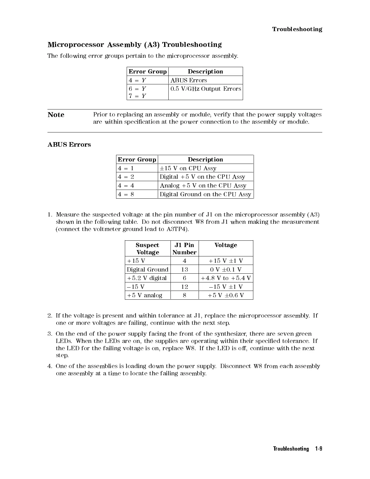
1.
Measure
the suspected
voltage at
the
pin
number
of
J1
on
the
microprocessor
assembly
(A3)
shown
in
the
following
table.
Do
not
disconnect
W8
from
J1
when
making
the
measurement
(connect
the
voltmeter
ground
lead to
A3TP4).
Suspect
V
oltage
J1
Pin
Number
V
oltage
+15
V
4 +15
V
6
1
V
Digital
Ground
13 0
V
6
0.1
V
+5.2
V
digital
6 +4.8
V
to
+5.4
V
0
15
V
12
0
15
V
6
1
V
+5
V
analog
8 +5
V
6
0.6
V
2.
If
the
voltage
is
present and
within tolerance
at J1,
replace the
microprocessor assembly
.If
one
or
more
voltages
are
failing,
continue
with
the
next
step
.
3. On the end of the
power supply facing the front of the synthesizer
, there are seven green
LEDs. When the LEDs are
on, the supplies are operating within their specied tolerance
.If
the LED for the failing voltage is
on, replace W8. If the LED is o, continue with the next
step.
4. One of the assemblies is loading down the power supply
. Disconnect W8 from each assembly
one assembly at a time to locate the failing assembly
.
Troubleshooting 1-9
 Loading...


