Troubleshooting
3. Measure
the voltage
at TP6
on the
microprocessor assembly
(A3) using
a
voltmeter
(connect
the voltmeter
ground lead
to A3TP4).
If the
voltage is
between 0
to
5
volts
,
continue
with
the next
step.
If the
voltage is
a
negative
voltage
,
continue
with
step
7.
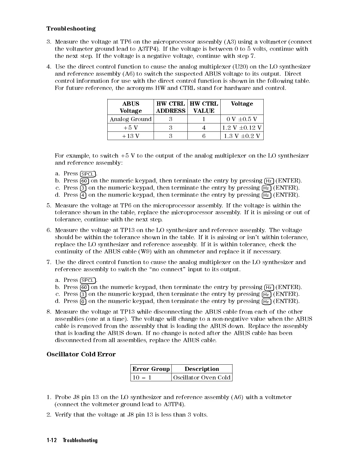
4. Use
the direct
control function
to cause
the
analog
multiplexer
(U20)
on
the
LO
synthesizer
and reference
assembly (A6)
to switch
the suspected
ABUS
voltage
to
its
output.
Direct
control information
for use
with the
direct control
function is
shown
in
the
following
table
.
For
future reference
, the
acronyms
HW
and
CTRL
stand
for
hardware
and
control.
ABUS
V
oltage
HW
CTRL
ADDRESS
HW
CTRL
V
ALUE
V
oltage
Analog
Ground
3 1 0
V
6
0.5
V
+5
V
3 4 1.2
V
6
0.12
V
+13
V
3 6 1.3
V
6
0.2
V
F
or
example
,
to switch
+5 V
to the
output of
the
analog
multiplexer
on
the
LO
synthesizer
and
reference
assembly:
a.
Press
4
SPCL
5
.
b.
Press
4
60
5
on
the
numeric
keypad,
then
terminate
the
entry
by
pressing
4
Hz
5
(ENTER).
c.
Press
4
3
5
on the
numeric
keypad,
then
terminate
the
entry
by
pressing
4
Hz
5
(ENTER).
d.
Press
4
4
5
on the
numeric
keypad,
then
terminate
the
entry
by
pressing
4
Hz
5
(ENTER).
5.
Measure
the
voltage
at
TP6
on
the
microprocessor
assembly
.
If
the
voltage
is
within
the
tolerance
shown
in
the
table
,
replace
the
microprocessor
assembly
.
If
it
is
missing or
out of
tolerance
,
continue
with
the
next
step
.
6.
Measure
the
voltage
at
TP13
on
the
LO
synthesizer
and
reference
assembly
.
The
voltage
should
be
within
the
tolerance
shown
in
the
table
.
If
it
is
missing
or
isn't
within
tolerance,
replace
the
LO
synthesizer
and
reference
assembly
.
If
it
is
within
tolerance
,
check
the
continuity
of
the
ABUS
cable
(W9)
with
an
ohmmeter
and
replace it
if
necessary
.
7.
Use
the
direct
control
function
to
cause
the
analog
multiplexer on
the LO
synthesizer
and
reference
assembly
to
switch
the
\no
connect"
input
to
its
output.
a.
Press
4
SPCL
5
.
b.
Press
4
60
5
on
the
numeric
keypad,
then
terminate
the
entry
by
pressing
4
Hz
5
(ENTER).
c.
Press
4
3
5
on
the numeric
keypad, then
terminate the
entry
by
pressing
4
Hz
5
(ENTER).
d.
Press
4
0
5
on
the numeric
keypad, then
terminate the
entry by
pressing
4
Hz
5
(ENTER).
8. Measure
the voltage
at TP13
while disconnecting
the ABUS
cable from
each of
the
other
assemblies
(one
at
a
time).
The
voltage
will
change
to
a
non-negative
value
when
the
ABUS
cable is removed from the assembly that is loading the ABUS down.
Replace the assembly
that is loading the ABUS down. If no change is noted after the ABUS cable has been
disconnected from all assemblies
, replace the ABUS cable
.
Oscillator Cold Error
Error Group Description
10 = 1 Oscillator Oven Cold
1. Probe J8 pin 13 on the LO synthesizer and reference assembly (A6) with a voltmeter
(connect the voltmeter ground lead to A3TP4).
2. Verify that the voltage at J8 pin 13 is less than 3 volts.
1-12 Troubleshooting
 Loading...


