Troubleshooting
If
the frequency
at J4
is incorrect
or missing,
check
the
continuity
of
W12
with
an
ohmmeter
.If
W12 has
continuity
,
replace
the
LO
synthesizer
and
reference
assembly
.
If
W12 is
opened, replace
W12.
If
the
frequency
at
J4
is
correct,
continue
with
this
procedure
.
5.
Disconnect the
frequency counter
from
J4
and
reconnect
W10
to
J4
through
an
SMC
tee
connector
.
6.
Using
an
oscilloscope
,
verify
that
the
voltage
at
the
tee
connector
is
4.5
Vp-p
6
0.5
Vp-p.
If
the
voltage
at
the
tee
connector
is
incorrect
or
missing,
replace
the
LO
synthesizer
and
reference
assembly
,
otherwise
,
continue
with
this
procedure
.
7.
Disconnect
the
external
10
MHz
time
base
from
the
synthesizer
and
connect
the
reference
output
of
the
synthesizer
to
the
reference
input
of
the
frequency
counter
.
8.
P
erform
steps
3
through
6
again.
If
steps
3
through
6
fail
with
the
external
10
MHz
time
base
disconnected,
replace the
LO
synthesizer
and
reference
assembly
,
otherwise
,
remove
the
SMC
tee
connector
,
reconnect
W10
to
J4,
and
continue
with
the
next
step
.
9.
Disconnect
W1
from
J7
on
the
LO
synthesizer
and
reference
assembly
and
connect
J7
to
the
input
of
the
frequency
counter
through
a
20
dB
attenuator
.
10.
Connect
a
voltmeter
to
P1
pin
2
on
the
LO
synthesizer
and
reference
assembly
(connect the
voltmeter
ground
lead
to
A3TP4).
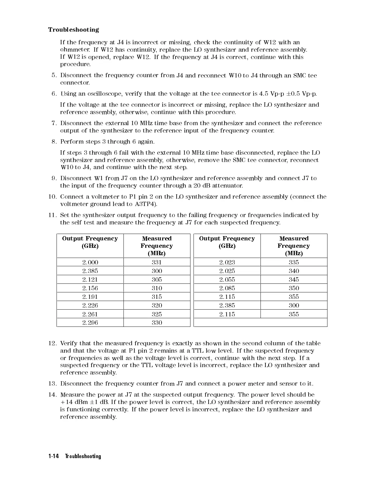
11.
Set
the
synthesizer
output
frequency
to
the
failing
frequency or
frequencies indicated
by
the
self
test
and
measure
the
frequency
at
J7
for
each
suspected frequency
.
Output
Frequency
(GHz)
Measured
Frequency
(MHz)
2.000 331
2.385 300
2.121 305
2.156 310
2.191 315
2.226 320
2.261 325
2.296 330
Output
Frequency
(GHz)
Measured
Frequency
(MHz)
2.023 335
2.025 340
2.055 345
2.085 350
2.115 355
2.385 300
2.115 355
12. V
erify that the measured frequency is exactly as shown in the
second column of the table
and that the voltage at P1 pin 2 remains at a TTL low level.
If the suspected frequency
or frequencies as well as the voltage level is correct, continue with the next step
.Ifa
suspected frequency or the TTL voltage level is incorrect, replace the LO synthesizer and
reference assembly
.
13.
Disconnect the frequency counter from J7 and connect a power meter and sensor to it.
14. Measure the power at J7 at the suspected output frequency. The power level should be
+14 dBm
6
1dB. If the power level is correct, the LO synthesizer and reference assembly
is functioning correctly. If the power level is incorrect, replace the LO synthesizer and
reference assembly.
1-14 Troubleshooting
 Loading...


