Troubleshooting
Y
O
Loop
and
Oset
Synthesizer
Assembly
(A7)
Troubleshooting
The
following
error
groups
pertain
to
the
Y
O
loop
and
oset
synthesizer assembly
.
Error Group Description
13 =
Y
Data Readback
Errors
14
=
Y
ABUS
Error
15
=
Y
Oset
Synthesizer
Incorrect
Frequency/Unlocked
Errors
Note
Prior
to
replacing
an assembly
or module
, verify
that
the
power
supply
voltages
are
within specication
at the
power connection
to
the
assembly
or
module
.
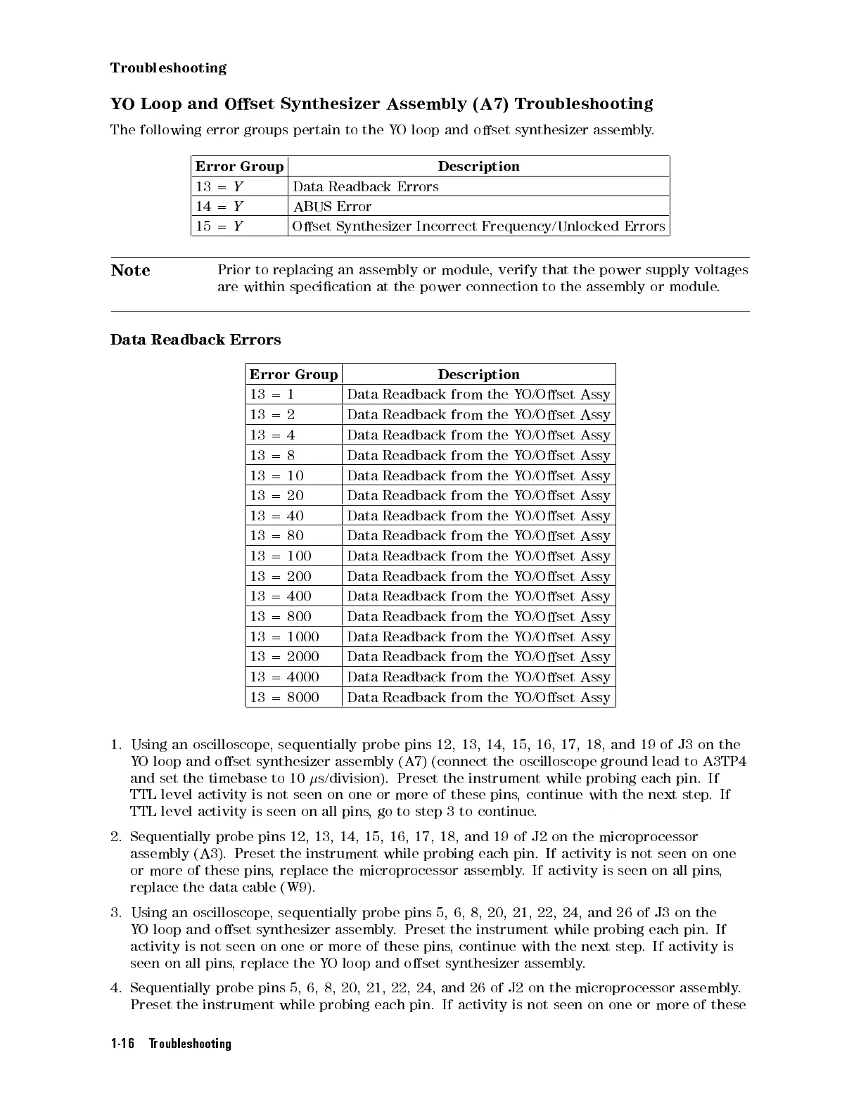
Data
Readback
Errors
Error
Group
Description
13
=
1
Data
Readback
from
the
Y
O/Oset
Assy
13
=
2
Data
Readback
from
the
Y
O/Oset
Assy
13
=
4
Data
Readback
from
the
Y
O/Oset
Assy
13
=
8
Data
Readback
from
the
Y
O/Oset
Assy
13 =
10
Data Readback
from the
Y
O/Oset
Assy
13
=
20
Data
Readback
from
the
Y
O/Oset
Assy
13
=
40
Data
Readback
from
the
YO/Oset
Assy
13
=
80
Data
Readback
from
the
Y
O/Oset
Assy
13
=
100
Data
Readback
from
the
Y
O/Oset
Assy
13
=
200
Data
Readback
from
the
Y
O/Oset
Assy
13
=
400
Data
Readback
from
the
Y
O/Oset
Assy
13 =
800
Data Readback
from
the
Y
O/Oset
Assy
13
=
1000
Data
Readback
from
the Y
O/Oset Assy
13 =
2000
Data Readback
from the
YO/Oset
Assy
13
=
4000
Data
Readback
from
the
Y
O/Oset Assy
13
=
8000
Data
Readback
from
the
Y
O/Oset
Assy
1.
Using an
oscilloscope,
sequentially probe
pins 12,
13,
14,
15,
16,
17,
18,
and
19
of
J3
on
the
Y
O
loop
and
oset
synthesizer
assembly
(A7)
(connect
the
oscilloscope
ground
lead
to
A3TP4
and set
the timebase to 10
s/division). Preset the instrument while probing each pin. If
TTL level activity is not seen on one or more of these
pins, continue with the next step
.If
TTL level activity is seen on all pins
, go to step
3 to continue
.
2. Sequentially probe pins 12, 13, 14, 15, 16, 17, 18, and 19
of J2 on the microprocessor
assembly (A3). Preset the instrument while probing each pin. If activity is not seen
on one
or more of these pins
, replace the microprocessor assembly
. If activity is seen
on all pins
,
replace the data cable (W9).
3. Using an oscilloscope, sequentially probe pins 5, 6, 8, 20, 21, 22, 24, and 26 of J3 on the
YO loop and oset synthesizer assembly. Preset the instrument while probing each pin. If
activity is not seen on one or more of these pins, continue with the next step. If activity is
seen on all pins, replace the YO loop and oset synthesizer assembly.
4. Sequentially probe pins 5, 6, 8, 20, 21, 22, 24, and 26 of J2 on the microprocessor assembly.
Preset the instrument while probing each pin. If activity is not seen on one or more of these
1-16 Troubleshooting
 Loading...


