Troubleshooting
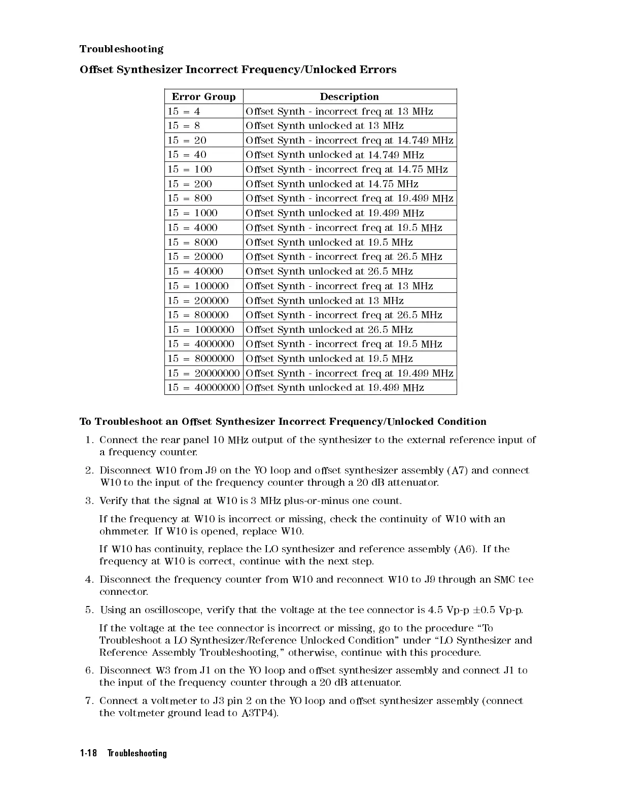
Oset
Synthesizer Incorrect
Frequency/Unlocked Errors
Error
Group
Description
15
=
4
Oset
Synth
- incorrect
freq at
13 MHz
15
=
8
Oset
Synth
unlocked
at
13
MHz
15
=
20
Oset
Synth
-
incorrect
freq
at 14.749
MHz
15
=40
Oset
Synth unlocked
at
14.749
MHz
15
=
100
Oset
Synth
-
incorrect
freq
at
14.75
MHz
15 =
200
Oset Synth
unlocked at
14.75
MHz
15
=
800
Oset
Synth
-
incorrect
freq
at
19.499
MHz
15
=
1000
Oset
Synth
unlocked
at 19.499
MHz
15
=
4000
Oset
Synth
-
incorrect
freq
at
19.5
MHz
15
=
8000
Oset
Synth
unlocked
at
19.5
MHz
15 =
20000
Oset Synth
-
incorrect
freq
at
26.5
MHz
15
=
40000
Oset
Synth
unlocked
at
26.5
MHz
15
=
100000
Oset
Synth
-
incorrect
freq
at
13
MHz
15
=
200000
Oset
Synth
unlocked
at
13
MHz
15
=
800000
Oset
Synth
-
incorrect
freq
at
26.5
MHz
15 =
1000000
Oset Synth
unlocked at
26.5 MHz
15
=
4000000
Oset
Synth
-
incorrect
freq
at
19.5
MHz
15
=
8000000
Oset
Synth
unlocked
at
19.5
MHz
15
=
20000000
Oset
Synth
-
incorrect
freq
at
19.499
MHz
15
=
40000000
Oset
Synth
unlocked
at
19.499
MHz
T
o
Troubleshoot
an
Oset
Synthesizer Incorrect
Frequency/Unlocked
Condition
1.
Connect
the
rear
panel
10 MHz
output of
the
synthesizer
to
the
external
reference
input
of
a
frequency
counter
.
2.
Disconnect
W10
from J9
on the
YO
loop and
oset
synthesizer
assembly
(A7)
and
connect
W10
to the
input
of
the
frequency
counter
through
a
20
dB
attenuator
.
3.
Verify
that
the
signal
at
W10
is
3
MHz
plus-or-minus
one
count.
If
the frequency
at W10
is
incorrect
or
missing,
check
the
continuity
of
W10
with
an
ohmmeter
.If
W10 is
opened, replace
W10.
If
W10
has
continuity
,
replace
the
LO
synthesizer
and
reference
assembly
(A6).
If
the
frequency at W10 is correct, continue with the next step
.
4. Disconnect the frequency counter from W10 and reconnect W10 to J9
through an SMC tee
connector.
5. Using an oscilloscope
, verify that the voltage at the tee connector is 4.5 Vp-p
6
0.5 Vp-p
.
If the voltage at the tee connector is incorrect or missing, go to the procedure \T
o
Troubleshoot a LO Synthesizer/Reference Unlocked Condition" under \LO Synthesizer and
Reference Assembly Troubleshooting," otherwise, continue with this procedure.
6. Disconnect W3 from J1 on the YO loop and oset synthesizer assembly and connect J1 to
the input of the frequency counter through a 20 dB attenuator.
7. Connect a voltmeter to J3 pin 2 on the YO loop and oset synthesizer assembly (connect
the voltmeter ground lead to A3TP4).
1-18 Troubleshooting
 Loading...


