Troubleshooting
T
o Troubleshoot
the RF
Detector Check
Error
1.
Install the
ALC assembly
in
the
service
position.
Refer
to
the
procedure
\ALC
Board
Assembly
A10" in
Chapter 5
of
this
manual.
2.
Set the
synthesizer frequency
to
2
GHz
and
set
the
output
power
level
to
+10
dBm.
3.
Measure the
power at
the RF
OUTPUT
connector
of
the
synthesizer
.
Record
the
power
level
in
the
space
provided:
dBm
4.
Measure
the
ALC
CTRL
SIG
OUT
(1
to
20
GHz)
at
J3
pin
32
on
the
ALC
assembly (A10)
with
a
voltmeter
(connect
the
voltmeter
ground
lead
to
A3TP4).
Record
the
voltage
level
in
the
space
provided:
V
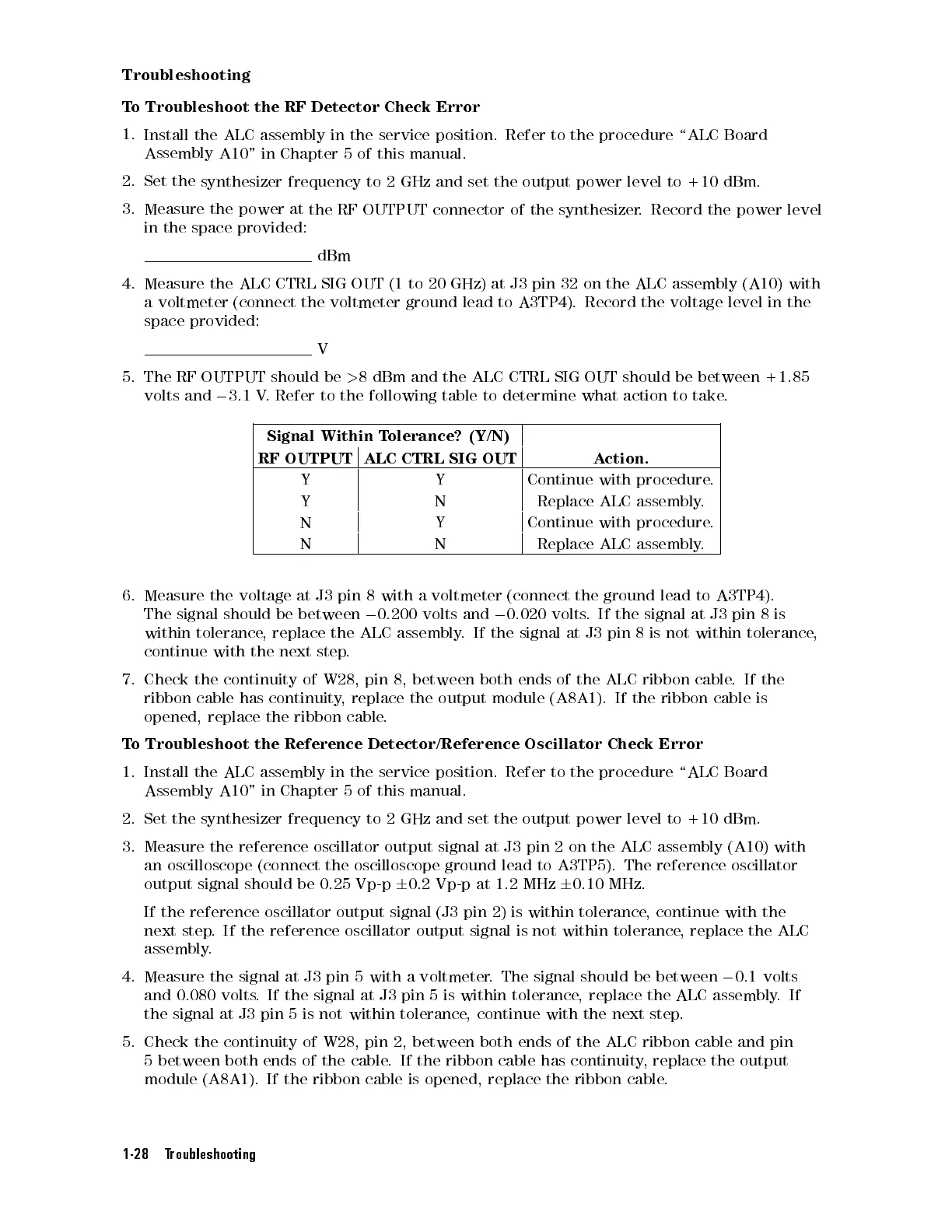
5.
The
RF
OUTPUT
should
be
>
8
dBm
and
the
ALC
CTRL
SIG
OUT should
be between
+1.85
volts
and
0
3.1
V
.
Refer
to
the
following
table
to
determine
what
action to
take.
Signal
Within
T
olerance?
(Y/N)
RF
OUTPUT
ALC
CTRL
SIG
OUT
A
ction.
Y Y Continue
with
procedure
.
Y N Replace
ALC assembly
.
N Y Continue
with
procedure
.
N N Replace
ALC
assembly
.
6.
Measure
the
voltage
at
J3
pin
8
with
a
voltmeter
(connect
the
ground
lead
to
A3TP4).
The
signal
should
be
between
0
0.200
volts
and
0
0.020
volts
.
If
the
signal
at
J3
pin
8
is
within
tolerance
,
replace
the
ALC
assembly
.
If
the
signal
at
J3
pin
8
is
not
within tolerance
,
continue
with
the
next
step
.
7.
Check
the
continuity
of
W28,
pin
8,
between
both
ends
of
the
ALC
ribbon
cable
.
If the
ribbon
cable
has
continuity
,
replace
the
output
module
(A8A1).
If
the
ribbon
cable
is
opened,
replace
the
ribbon
cable
.
T
o
Troubleshoot
the
Reference
Detector/Reference
Oscillator
Check
Error
1.
Install
the
ALC
assembly
in
the
service
position.
Refer to
the procedure
\ALC Board
Assembly
A10"
in
Chapter
5
of
this
manual.
2.
Set
the
synthesizer
frequency
to
2
GHz and
set the
output power
level to
+10 dBm.
3. Measure the reference oscillator output signal at J3
pin 2 on the ALC assembly (A10) with
an oscilloscope (connect the oscilloscope ground lead to A3TP5). The
reference oscillator
output signal should be 0.25 Vp-p
6
0.2 Vp-p at 1.2
MHz
6
0.10 MHz.
If the reference oscillator output signal (J3 pin 2) is within tolerance
, continue with the
next step
. If the reference oscillator output signal is not within tolerance
, replace the ALC
assembly.
4. Measure the signal at J3 pin 5 with a voltmeter
. The signal should be between
0
0.1 volts
and 0.080 volts. If the signal at J3 pin 5 is within tolerance, replace the ALC assembly.If
the signal at J3 pin 5 is not within tolerance, continue with the next step.
5. Check the continuity of W28, pin 2, between both ends of the ALC ribbon cable and pin
5 between both ends of the cable. If the ribbon cable has continuity, replace the output
module (A8A1). If the ribbon cable is opened, replace the ribbon cable.
1-28 Troubleshooting
 Loading...


