Troubleshooting
4. Check
the continuity
of the
pins shown
in
the
above
table
between
both
ends
of
the
ALC
ribbon cable
(W28). F
or example
, check
the
continuity
of
pin
15
between
both
ends
of
the
cable,
pin 26
between both
ends of
the
cable
,
etc
.
If the
ribbon cable
has
continuity
,
continue
with
the
next
step
.
If
the
ribbon
cable
is
opened, replace
the ribbon
cable
.
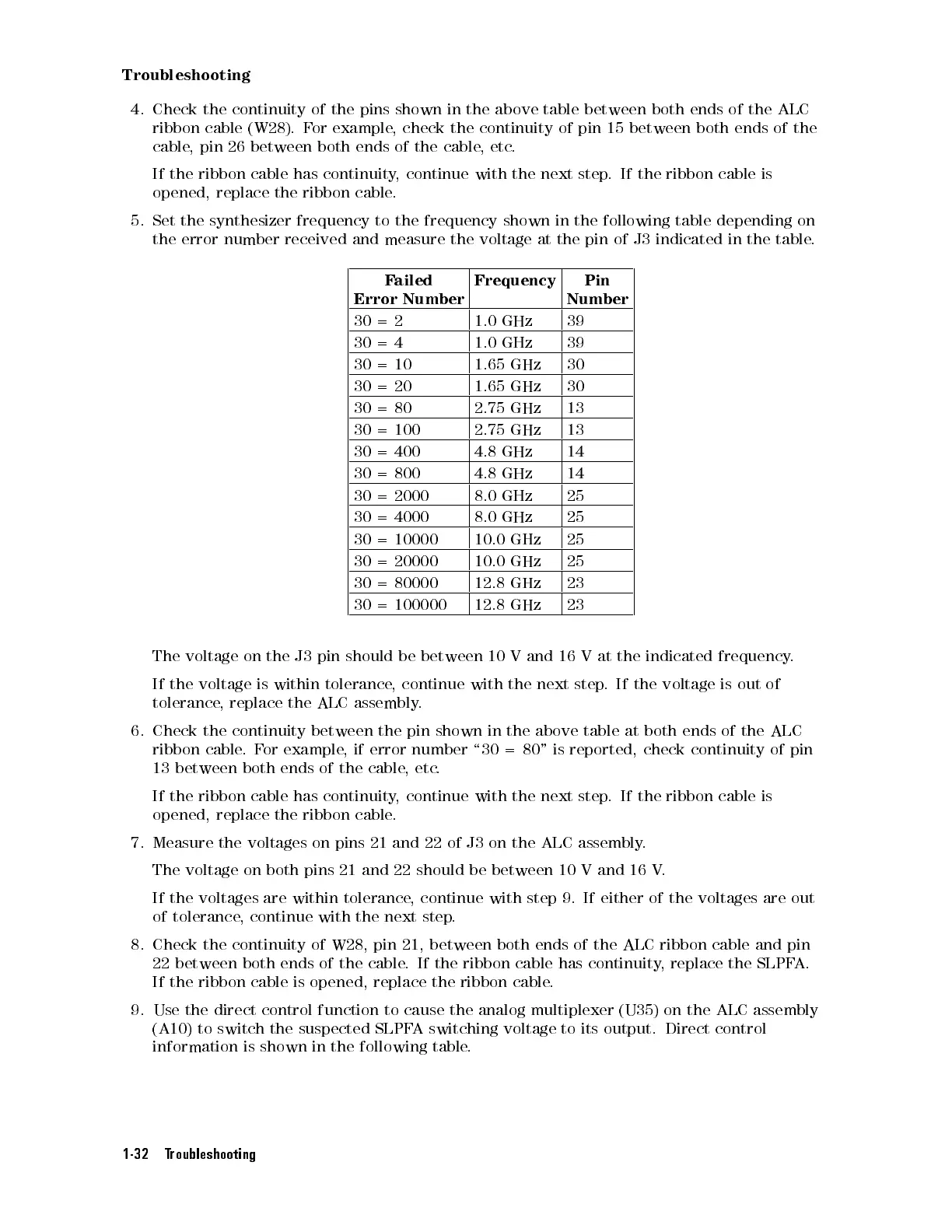
5. Set
the
synthesizer
frequency
to
the
frequency
shown
in
the
following
table
depending
on
the error
number
received
and
measure
the
voltage
at
the
pin
of
J3
indicated
in
the
table
.
F
ailed
Error
Number
Frequency Pin
Number
30
=
2
1.0
GHz
39
30 =
4
1.0 GHz 39
30
=
10
1.65
GHz
30
30
=
20
1.65
GHz
30
30
=
80
2.75
GHz
13
30
=
100
2.75
GHz
13
30
=
400
4.8
GHz
14
30
=
800
4.8
GHz
14
30 =
2000
8.0 GHz 25
30
=
4000
8.0
GHz
25
30
=
10000
10.0
GHz
25
30
=
20000
10.0
GHz
25
30
= 80000
12.8
GHz
23
30
=
100000
12.8
GHz
23
The
voltage
on
the
J3
pin
should
be
between
10
V
and
16
V
at
the
indicated
frequency
.
If
the
voltage
is
within
tolerance
,
continue
with
the
next
step
.
If
the
voltage
is
out
of
tolerance
,
replace
the
ALC
assembly
.
6. Check
the
continuity
between
the
pin
shown
in
the
above
table
at
both
ends
of
the
ALC
ribbon
cable
.
F
or
example
,
if
error
number
\30
=
80"
is reported,
check continuity
of pin
13
between
both
ends
of
the
cable
,
etc
.
If
the
ribbon
cable
has
continuity
,
continue
with
the
next
step
.
If the
ribbon cable
is
opened,
replace
the
ribbon
cable
.
7.
Measure
the
voltages
on
pins
21
and
22
of
J3
on
the
ALC
assembly
.
The voltage on both pins 21 and 22 should be between 10 V and 16 V
.
If the voltages are within tolerance
, continue with step 9. If either of the voltages are out
of tolerance
, continue with the next step
.
8. Check the continuity of W28, pin 21, between both ends of the ALC ribbon cable and pin
22 between both ends of the
cable. If the ribbon cable has continuity
, replace the SLPF
A.
If the ribbon cable is opened, replace
the ribbon cable
.
9. Use the direct control function to cause the analog multiplexer (U35) on the ALC assembly
(A10) to switch the suspected SLPFA switching voltage to its output. Direct control
information is shown in the following table.
1-32 Troubleshooting
 Loading...


