Getting Started 1
N1913/1914A Installation Guide 19
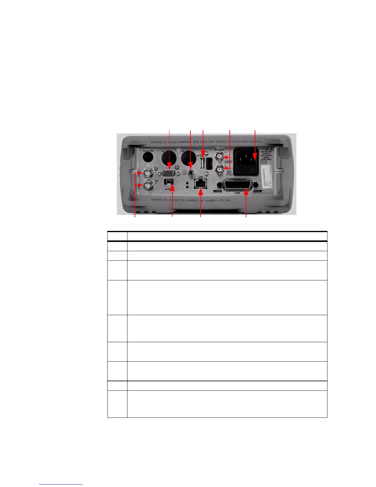
Rear Panel Connections
The following connections are available on the rear panel. To setup the
remote interfaces, refer to Remote Interface Configurations on page 20.
No. Connections
1 VGA Output (Option 010)
2 Ground Connector
3 USB Type A port (Option 008, Option 009)
This USB port is solely for U2000 Series power sensors usage only.
4 Recorder 1/2
Recorder output (two outputs are fitted to dual channel meters) connections are
made via BNC connectors. This output produces a DC voltage that corresponds
to the power level of the channel input.
5AC Inlet
This power meter has an auto configuring power supply. This allows it to operate
over a range of voltages without manually being set to a certain voltage.
6 Trig In/Trig Out
Trigger input and output connections are made via BNC connectors.
7USB Mini-B port
This USB port is used for remote interface connection.
8LAN
9GPIB
This connector allows the power meter to be controlled remotely using the
General Purpose Interface Bus.
 Loading...


