4
(1) Pliers
(1) Hammer
(1) AdjustableWrench(orsocketset)
(1) 9/16"OpenEndorBoxEndWrench
(2) 7/16"OpenEndorBoxEndWrench
(2) 1/2"OpenEndorBoxEndWrench
TOOLS REQUIRED FOR ASSEMBLY
REMOVAL OF PARTS FROM CARTON
• Removetheloosepartsandthehardwarepackagesfrom
thecarton.Layoutallpartsandhardwareandidentify
usingtheillustrationsonpages2and3.
IMPORTANT: Youwillnotneedallofthepartssuppliedwith
yourblade.Disposeofunusedpartsafteryouhavenished
assemblingtheblade.
NOTE: Righthand(R.H.)andlefthand(L.H.)aredetermined
fromtheoperatorspositionwhileseatedonthetractor.
ENGLISH
CAUTION: Do notbeginassemblinguntil
thetractorengine,mufflerandexhaust
deectorhavebeenallowedtocooloff.
TRACTOR PREPARATION
• Allowengine,mufflerandexhaustdeectortocoolbefore
beginning.
• Refertotractorowner'smanualtoremovemowerdeck
oranyotherattachmentyoumayhavemountedtoyour
tractor.Markallloosepartsandsavetoreuse.
• Youmayneedtoremovethebrowningshieldfromthe
frontofsometractormodelsforbetteraccess.
USE THE INSTRUCTIONS IN STEP 1 IF YOUR
TRACTOR HAS A SINGLE FRONT BRACKET
FOR ATTACHING THE MOWER DECK
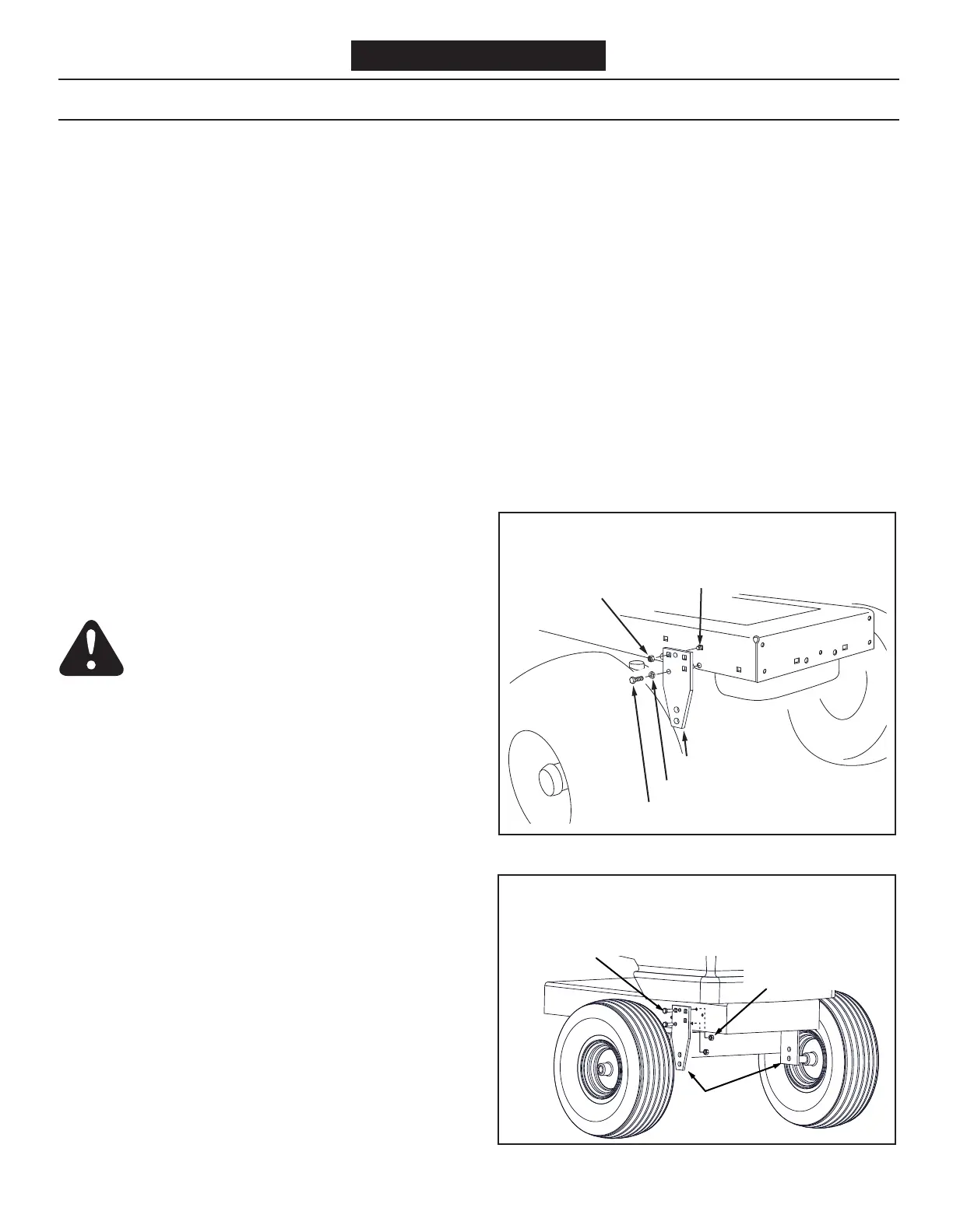
STEP 1: (SEE FIGURE 1)
Refertopage6forexamplesofhowtoattachtheFrame
Bracketstosomeothertractormodels.
• Holdtheframebracketsothatthetwoholesareat
thebottomandplaceitagainstthesideofthetractor
frameinfrontofthefrontaxle.Aligntwoupperholes
inthebracketwithtwoholesinthetractorframe.Turn
thebracketoverifnecessary.Attachthebracketusing
theappropriatehardware.
FIGURE 1B
FIGURE 1A
3/8" x 1" HEX BOLT (Q)
FRAME BRACKET
3/8" NYLOCK
NUT (I)
3/8" x 1"
CARRIAGE BOLT (F)
3/8" LOCK WASHER (R)
SEARS 917 SERIES TRACTOR FRAME
JOHN DEERE LT TRACTOR FRAME
FRAME
BRACKETS
5/16" x 1"
HEX BOLTS (C)
5/16" NYLOCK
NUTS (H)
ASSEMBLY
SKIP TO STEP 2 IF YOUR TRACTOR HAS TWO
FRONT BRACKETS FOR ATTACHING THE
MOWER DECK.
 Loading...