9
FIGURE 16 (Right Hand Side View)
FIGURE 14 (Left Hand Side View)
(Right Hand Side View)
FIGURE 15
ENGLISH
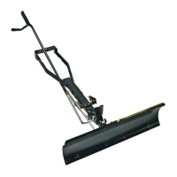
STEP 14: (SEE FIGURE 14)
• Assembleballendofcontrolcableupthroughholein
cableendttingand pull untilballslipsinside curled
edgeofttingasshown.Ifballwon'tslipunderedgeof
curlitwillneedtobeinsertedthroughopenendofcurl.
• Assemblea1/4"x1-1/4"hexboltdownthroughthecable
endtting,the5/8"longspacerandthelefthandhole
inthechannelassembly.Securewitha1/4"nylocknut.
Tighten.
NOTE: Makesurethecablemountbracketisalignedwith
thecableendttingasshowntopreventbindingofcable.
Attachtheotherendofthecontrolcableinalaterstep.
STEP 15: (SEE FIGURE 15)
• Toattachthebladetothechannelassembly,alignthe
notchedholesinthepivotplatewiththenotchedholesin
theblade.Inserta1/8"x1-1/4"cotterpindownthrough
theholeatthebendinthebladepivotshaft.Spreadthe
endsofthepin.Fromtheleftsideinsertthebladepivot
shaft,bendfacingup,throughthenotchedholes.Secure
theshaftwithanother1/8"x1-1/4"cotterpinthroughthe
endholeintheshaft.Spreadtheendsofthepin.
• Removetheplasticcapandone3/8"hexnutfromthebolt
inthebladeadjustspring.Adjusttheremaining3/8"hex
nutdownapproximately1"ontotheboltthreads.Hook
thespringoverthespringmountrodasshown.Place
theboltupthroughtheholeinthetopedgeoftheblade
andreassembletheother3/8"hexnutandtightendown
againstthetopedgeoftheblade.Replacetheplastic
capovertheendoftheboltthreads.
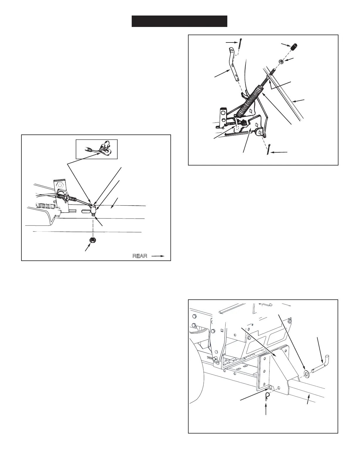
STEP 16: (SEE FIGURE 16)
• Assemblethe1/2"washerontothechannelpivotpin.
• Attachthechannelassemblytothetractorbyplacingthe
endofthechannelassemblyupinsidethepivotsupport
bracketonthetractor.Aligntheholeinthepivotsupport
bracketwiththesecond holeinthechannelassembly.
Insertthechannelpivotpinthroughthealignedholes
fromtheleftsideandsecurewithasmallhairpincotter
pushedallthewaythroughtotheloopend.
NOTE: Allhairpincottersonthissnowbladeshouldbe
pushedthroughtotheirloopend.
1/4" x 1-1/4"
HEX BOLT (B)
CABLE END
FITTING
1/4" NYLOCK NUT (G)
5/8" SPACER (T)
CHANNEL
ASSEMBLY
HOLE
REAR
3/8" HEX NUT
(TOP)
PLASTIC
CAP
3/8" HEX NUT
(BOTTOM)
BLADE
1/8" x 1-1/4"
COTTER PIN (O)
BLADE
PIVOT
SHAFT
SPRING
MOUNT
ROD (Z)
BLADE
ADJUST
SPRING
1/8" x 1-1/4"
COTTER
PIN (O)
PIVOT PLATE
1/2" WASHER (S)
CHANNEL
PIVOT PIN (AA)
CHANNEL
ASSEMBLY
HOLE IN END OF
CHANNEL ASSEMBLY
SMALL HAIRPIN
COTTER (N)
PIVOT SUPPORT
BRACKET
 Loading...