Tarla başı dönüşlerde ayaklar, otomatk yardımıyla kaldırılmalıdır.
Böylece ayakların deformasyonu da önlenr (Şek. 17).
Öneml Not: Otomatk kolunu çekerken mutlaka otomatk koluna
bağlı olan halatları kullanınız. Otomatğn devreye greblmes çn
mbzern tekerlek kısmında hareket olması gerekmektedr. Bu
vesleyle hareket halndek mbzer halatlar çıkarılarak makne
üzernde bulunan kol vasıtasıyla ekm-yol durumuna getrmeye
çalışmak çok tehlkeldr. Mbzer hareket halnde ken otomatk
sstemnn üzernde bulunan dşl zncr sstemn kontrol amaçlı
yaklaşmanız ve elnz sürmenz tehlkel sonuçlar doğurablr.
Otomatk sstemn kontrol etmek çn maknenn durduğuna emn
olunuz.
7.10. Ekc Dsklern Hdrolk Sstem İle Hareket
Hdrolkl makne sstemnn
görev makney yolda taşıma ve
tarlada ekm durumuna getrmektr.
Böylece gömücü ayakların tamamı,
sağ yarısı veya sol yarısı hdrolk lft
sayesnde ndrerek ekm şlemne
başlan ır. Bu şl em maknede
bulunan (12'l) mbzerde 1 adet, dğer
mbzerlerde 2 adet lft sayesnde
kolayca yapılır. Ekc ayakların
t a m a m ı y a d a y ar ı sı m a k n e
merkeznde bulunan hdrolk valf
sayesnde hareket ettrlr (Şek. 16).
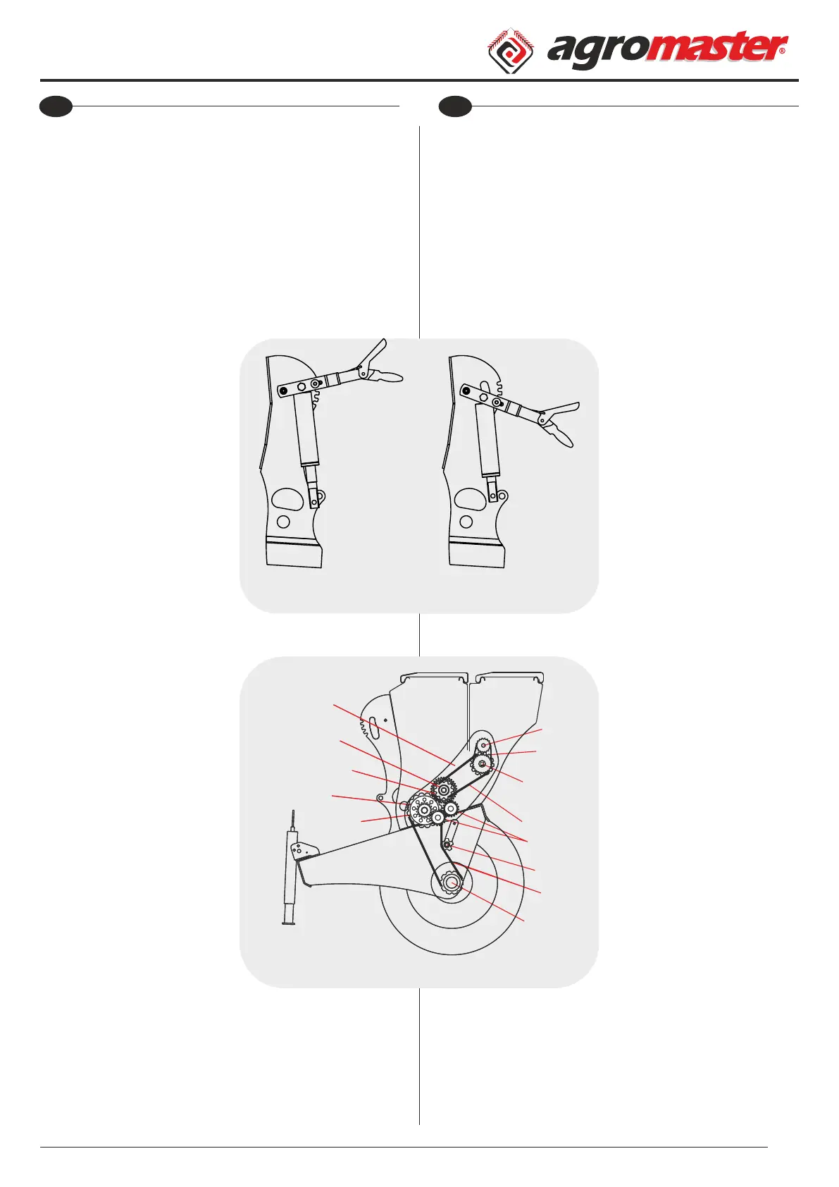
7.11. Hareket İletm Sstem
A. Tohum Sandığı
B. Gübre Sandığı
1. Dşl Muhafazası
2. Gübre Hareket Dşls
3. Gübre Sandığı Dşls
4. Yaprak Dşl
5. 32'lk Şaft Dşls
6. Karıştırıcı Dşls
7. 1/2 08b Zncr
8. Gübre Sandığı Ve Karıştırıcı
Hareket Ortak Dşls
9. 2040 Zncr
10. Kavrama Dşls
11. Zncr Gerdrme
12. 2040 Zncr
13. Porya Dşls
Ekm maknelernde tohum ve gübre ayarının maknenn çeklme
hızına göre değşmemes çn ekc ve gübre atıcı mller hareketn
maknenn tekerlek poyrasından almaktadır. Tekerlek çapında
meydana gelen değşklkler, (lastk basıncı) çapın küçülmes ve
atılacak tohum le gübre ayarının stenlen değerde atılmasını
mümkün kılmayacaktır. Porya dşl kovanından alınan hareket, zncr
aracılığı le tohum sandığı başındak ana hareket dşlsne ve oradan da
dğer dşllere letlr (Şekl 17).
While turning at the ends of eld foot should be lifted by means of
the automatic. By this way damages are prevented (Fig. 19).
Important Note: While pulling the automatic lever, you should use
the ropes that connected to automatic lever. Wheels of seed drill
should be moved for movement of automatic system. While machine
is moving it is dangerous to change the machine status. While the
seed drill is moving, it is dangerous to approach to the seed drill for
checking the gear chain system and touching it.
Be sure that the machine is stopped while checking the automatic
system.
7.10. Movement Of Disc Coulter By Means Of The Hydraulic
System
Hydraulic system ensures to
transporting of machine on the road
and getting to working position.
Drilling coulters are lowered by
means of the hydraulic system to
start sowing. This process is done by
means of the hydraulic lift of
machine (there is one lift on 12 rows
seed drill and two on other seed
drills). Sowing feet are mowed by
means of the hydraulic valve on the
center of machine (Fig. 18).
7.11. Movement Transmision System
A. Seed Hopper
B. Fertilizer Hopper
1. Gear Protection
2. Drive Gear Of Fertilizer
3. Seed Hopper Gear
4. Sprocket Gear
5. Shaft Gear 32
6. Mixer Gear
7. 1/2 08b Chain
8. Common Drive Gear Of Fertilizer
Hopper And Mixer
9. 2040 Chain
10. Clutch Gear
11. Chain Tensioning
12. 2040 Chain
13. Hub Gear
Adjustments of seed and fertilizer are changed according to
machine speed, for preventing of these changes sowing and fertilizer
spreading axles get their movement from tractor's wheel hub. The
amount of seed and fertilizer which required to thrown away can be
changed due to the changes in wheel diameter (tire pressure). The
movement of hub gear is forwarded to main movement gear by
means of chain then is forwarded to other gears (Fig. 19).
7.8. Gübre Sandığı
Tohum sandığında olduğu gb
gübre sandığı da 1,5 mm sacın preste
şekllendrlmes le mal edlmş ve
üstten alta doğru daralan şeklde
yapılmıştır. Gübre sandığı tohum
sandığının arka kısmına monte
edlmştr. Gübre sandığının üst
kısmına, cıvata, somun taş ve gübre
topraklarının elenmes çn gübre
eleğ konulmuştur. Sandık çersne gübrenn köprü yapmasını
önlemek çn mekank br karıştırıcı bağlanmıştır (Şekl 15). Gübre
atma sstem, alümnyum gübre makaraları, gübre hücrelernden ve
gübre ayar kollarından oluşmuştur. Gübre mktarı ayarı, derece kolu
yardımı le makaralar üzerndek sürgü sacının hareketyle yapılır.
Gübre ml ve karıştırıcı ml dşller yardımıyla, hareketn tekerden
almaktadır (Şekl 19). Ekm sırasında ve ekm öncesnde gübrelern
rutubet almamasına dkkat edlmeldr. Rutubet alarak çamurlaşan
gübre, gübre atan makne oluklarına sıvanarak maknenn ayarını
bozar. Nemn kaybeden gübre sertleşr. Makara ve gübre hücres
arasına dolar, sıkışmalarına sebebyet verr.
Öneml Not: Gübre sandığının çersnde bulunan elek yabancı
maddelern gübre makaralarına ulaşıp zarar vermesn önlemek
maksadıyla takılmıştır. Aynı zamanda bu sac tabana yakın kısımdak
karıştırıcı düzeneğne de muhafaza görev yapar. Bu sacın çıkarılması
tehlkel sonuçlar doğurablr. Gübre sandığı kapağının açılması şlem
ellernzn sıkışmasını önlemek çn dama üzernde bulunan kulplar
vasıtasıyla yapılmalıdır. Mbzer hareket halnde ken gübre sandığına
elnz sokmayınız ve gübre koymaya çalışmayınız.
7.9. Ekc Dsklern Mekank Sstem İle Hareket
Mekank sstemnn görev makney yolda taşıma ve tarlada ekm
durumuna getrmektr. Hareketn
ana hareket mlne bağlı otomatk
dşlsnden almaktadır. Otomatk
üzerndek kolun çeklmesyle,
otomatk gövde 0,5 tur döner ve
mandal yardımıyla durur. Böylece
gömücü ayaklar nerken tohum ve
gübre atıcı mller döner ve makne
ekm şlemne başlar (Şek. 14).
Otomatk sstemnde bulunan
dşllern çnde sgorta vazfes
yapması amacıyla yerleştrlen pmler
bulunmaktadır. Bu pmler yaprak
dşlnn çnde ve çelk dşlnn çnde
olmak üzere k adettr. Yaprak dşlde
bulunan sgorta pm alt düzende
meyd a n a g e leblece k s ı k ı ş m alar
sonucunda makneye daha büyük
zararlar verlmemes çn keslerek
hareket durdurur.
Tohum sandığına tahrk veren 32'lk
mle bağlı olan çelk dşlnn çnde
bulunan dğer br sgorta pm se tohum
kutusunda oluşablecek sıkışmalar
sonucunda devreye grerek hareket
durdurur ve makney emnyete alır.
Sgorta pmlernn devreye grerek
makne hareketnn durması bu pmlern
keslmes anlamına gelr ve çalışmaya
başlamak çn yenler le değştrlmes
gerekmektedr (Şek. 15). Otomatk
kolunun 2. kez çeklmesyle ekc ayaklar
kalkar, tohum ve gübre mllernn
hareket keslr. Böylece mbzer yol
durumuna geçmş olur. Otomatk zncr
gergnlğ y ayarlanmalıdır. Zncrn aşırı gergn veya gevşek oluşu
zncrn kopmasına neden olur. Zncr ayarı çn gerdrmenn kanallı
yatağı üzerndek cıvata kullanılır. Otomatk ayar koluna bağlanan
pler yardımıyla sürücü otomatğ traktör üzernden kumanda eder.
7.8. Fertilizer Hopper
Fertilizer hopper is made from 1, 5
mm thickness sheet and becomes
tight from top to bottom (like seed
hopp e r). Fer t ilize r h opper is
assembled to behind of seed hopper.
There are bolt, nut and also fertilizer
sieve (for eliminating of fertilizer) on
the top of fertilizer hopper. A
mechanical mixer is attached into the hopper to prevent the jamming
of fertilizer due to its weight and moisture (Fig. 15).
Fertilizer throwing system is composed of aluminum reels, fertilizer
cells and fertilizer adjusting levers. The amount of fertilizer is adjusted
with the sliding sheet on the reels by means of degree lever. Fertilizer
and mixing axles are moved by gears which take power from wheel
(Fig. 19).
You should protect the fertilizer against the moisture during the
sowing and before sowing. Machine adjustment can be broken due to
jamming of moist fertilizer to the holes.
Important Note: There is a sieve in the fertilizer hopper for
preventing the damage of fertilizer reels composed of foreign matters
and also this sieve protects the mixing mechanism. Taking out this
sieve can be caused dangerous results. While opening and closing the
lid of fertilizer hopper, use the handles on the top of the hopper lid and
be careful your hands not to jam. Don't insert your hands in to the
fertilizer hopper and don't try to ll fertilizer while the machine is
moving.
7.9. The Movement Of Disc Coulter With Mechanical System
The main functions of mechanical system are transporting of
machine on the road and getting to
sowing position on the eld. The
mechanical system is moved by
automatic gear that connected to
main movement axle. Automatic
body turns 0, 5 tours by pulling the
bar on the automatic and it is
stopped by means of the catch. While
drill coulters are lowering, seed and
fertilizer spreading axles turn and
machine starts to sow (Fig. 16). There
are two security pins in gears of
automatic system. One of is in the
sprocket gear and the other one is in
clutch gear. Security pins on sprocket
gear are broken due to jamming in the
seeder s y stem and s topped the
movement to prevent the damages. Also
another security pin on clutch gear is
broken due to jamming in the seed
hopper and stopped the movement to
prevent the damages. For starting to
work again, broken security pins should
be replaced. (Fig. 17).
By pullng the automatc lever second
tme, sowng feet are lfted so the
movement of fertlzer and seed axles s
stopped. By ths way the seed drll gets to
the transportaton poston. Tensonng
of automatc chan must be adjusted
properly. Loosen or extremely tghtened
chan can be broken. Adjustment of the chan s adjusted by means of
the bolt on the tensonng bearng. Drver can control the automatc
from the tractor by means of the ropes whch connected to automatc
adjustng lever.
EN
Operator's Manual
BM
Kullanım Kılavuzu
19
TREN
Operator's Manual
BM
Kullanım Kılavuzu
18
TR
Fg. 15
Şek. 15
Fg. 16
Şek. 16
Fg. 17
Şek. 17
Fg. 18
Şek. 18
Fg. 19
Şek. 19
1
2
3
4
5
6
7
8
9
10
11
12
13
A
B
 Loading...