86
Using the Password to Access Calibration or Change the Password
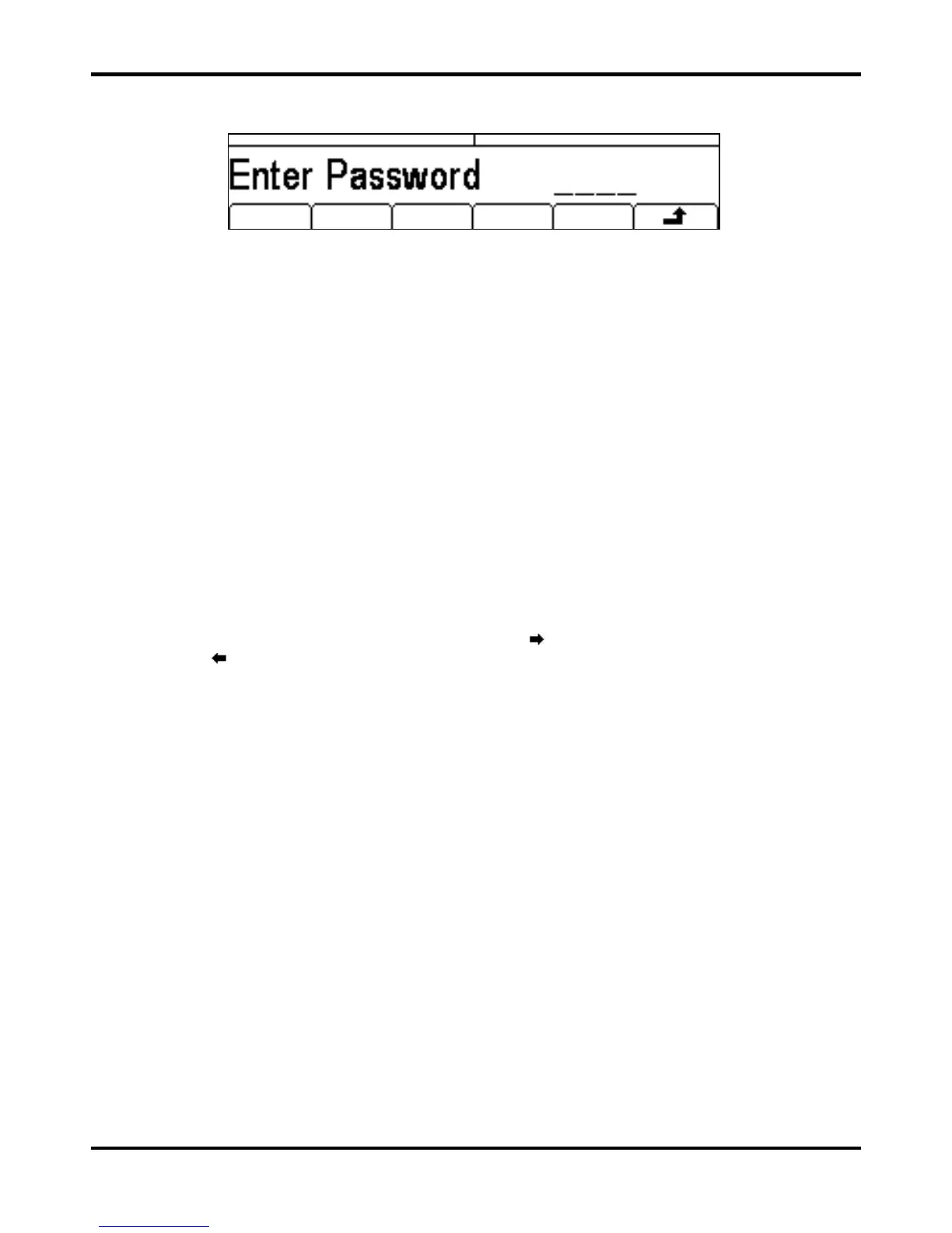
With the password set, pressing calib on the utility screen will now show:
When the correct password has been entered from the keyboard the display changes to the
opening screen of the calibration routine and calibration can proceed as described in the Calibration
Routine section. If an incorrect password is entered the message Incorrect Password
Please Try Again will pop up for two seconds before the display reverts to the Utility menu.
With the opening screen of the calibration routine displayed after correctly entering the password,
the password can be changed by pressing Pswrd soft-key and following the procedure described
in Setting the Password. If the password is set to 0000 again, password protection is removed.
The password is held in flash memory and will not be lost when the memory battery back−up is lost.
In the event of the password being forgotten, contact the manufacturer for help in resetting the
instrument.
Calibration Routine
The calibration procedure proper is entered by pressing Cont’n on the top level Calibration menu;
pressing
Done returns the display to the Utilty menu. Pressing Tests calls a menu of basic
hardware checks used at production test; these are largely self−explanatory but details can be
found in the Service Manual if required.
At each calibration step the display changes to prompt the user to adjust the KNOB or cursor keys,
until the reading on the specified instrument is at the value given. The cursor keys provide coarse
adjustment, and the KNOB fine adjustment. Pressing
increments the procedure to the next step;
pressing
decrements back to the previous step. Pressing CH1/CH2 jumps to the first calibration
step for Channel 1 or Channel 2 respectively. Alternatively, pressing
Cancel returns the display
to the final calibration screen at which the user can choose to either
Save , recall or
Restart .
Each calibration step allows a calibration value to be calibrated. The screen messages specify the
instrument to use for measurement, the connector to connect it to, the value to adjust for and the
method of adjustment
The full procedure is as follows:
 Loading...