EasyManua.ls Logo

Aiphone LEF-10 User Manual

Aiphone LEF-10
16 pages
To Next Page IconTo Next Page
Page #1 background imageLoading...
Page #1 background image
– 1 –
LEF Series
OPEN VOICE SELECTIVE CALL INTERCOM
INSTALLATION & OPERATION MANUAL
LEF-3 (3-call master)
LEF-5 (5-call master)
LEF-10 (10-call master)
LEF-10S (10-call master w/all call button)
Models:
* LEF-5W, LEF-10W & LEF-10SW:
w/Terminal Box prewired
(Not available in North America)
PRECAUTIONS
WARNING (Negligence could result in death or serious injury.)
1.
2.
3.
4.
5.
6.
7.
8.
9.
10.
Do not dismantle or alter the unit. Fire or electric shock could result.
Keep the unit away from water or any other liquid. Fire or electric shock could result.
For power supply, use Aiphone power supply model specified for use with system. If non-specified product is used, fire or malfunction
could result.
Do not connect any non-specified power source to the +, - terminals. Also, do not install two power supplies in parallel to a single input.
Fire or damage to the unit could result.
Do not use power supply with a voltage other than specified. Fire or electric shock could result.
Keep AC cord from being marred or crushed. If the AC cord is damaged, fire or electric shock could result.
Do not plug or unplug unit with wet hands. Electric shock could result.
Insert AC plug completely and securely into AC outlet. Otherwise, fire or electric shock could result.
Periodically check for and remove dust on the power plug. If dust is left, it could cause the power plug to heat up, resulting in fire.
Do not put any metal or flammable material into the unit through the openings. Fire, electric shock, or unit trouble could result.
1.
2.
3.
4.
5.
6.
7.
CAUTION (Negligence could result in injury to people or damage to property.)
Do not install or make any wire terminations while power supply is plugged in. It can cause electrical shock or damage to the unit.
When mounting the unit on a wall, install the unit in a convenient location, but not where it could be jarred or bumped. Injury could result.
Before turning on power, make sure wires are not crossed or shorted. If not, fire or electric shock could result.
Do not place or install the unit in the locations subject to frequent vibration or impact. If the unit falls, injury to people or damage to the
unit could result.
Do not put anything on the unit or cover the unit with cloth, etc. Fire or unit trouble could result.
Do not install the unit in any of the following locations. Fire, electric shock, or unit trouble could result.
* Places under direct sunlight (except door station).
* Near heating equipment that varies in temperature.
* Places subject to dust, oil, chemicals, hydrogen sulfide (hot spring).
* Places subject to moisture and humidity extremes, such as bathrooms, cellars, greenhouses, etc.
* Places where the temperature is quite low, such as inside a refrigerated area or in front of an air conditioner.
* Places subject to steam or smoke (near heating or cooking surfaces).
* Where noise generating devices such as dimmer switches or inverter electrical appliances are closeby.
* Locations subject to frequent vibration or impact.
* Locations subject to extremely powerful electric fields.
The unit must be installed and wired by a qualified technician.
1.
2.
3.
4.
5.
6.
7.
8.
9.
GENERAL PRECAUTIONS
Keep the unit more than 1m (3.3') away from radio or TV sets.
Keep the intercom wires more than 30cm (12'') away from AC 100-240V wiring. AC induced noise and/or unit malfunction could result.
Comply with all third party manufacturing specifications that will be used with this system.
Using a mobile phone or professional-use radio equipment such as walkie-talkie close to the system may cause a malfunction.
The unit can be damaged if dropped. Handle with care.
The unit will not work during power failure.
In areas where broadcasting station antennas are closeby, the intercom system may be affected by radio frequency interference.
All the units, except for door stations, are designed for indoor use only. Do not use at outdoor locations.
This product, providing door release, should not be used as a crime prevention device.
Prohibited Do not dismantle unit Keep unit away from water General precautions

Other manuals for Aiphone LEF-10

Question and Answer IconNeed help?

Do you have a question about the Aiphone LEF-10 and is the answer not in the manual?

Aiphone LEF-10 Specifications

General IconGeneral
MaterialAcrylonitrile butadiene styrene (ABS)
Product typeMaster Station
Mounting typeDesk/Wall
Product colorBlack, Grey, White
Brand compatibilityAiphone
Power consumption300 mA
Weight and Dimensions IconWeight and Dimensions
Depth55 mm
Width190 mm
Height206 mm
Weight650 g

Summary

Safety Precautions and Warnings

General Safety Precautions

Covers general safety icons, prohibitions, and precautions for unit operation and environment.

Electrical and Fire Hazard Warnings

Detailed warnings regarding dismantling, water exposure, power supply, wiring, and internal components.

Operational and Environmental Cautions

Cautions related to installation, wire termination, unit placement, and environmental factors.

System Installation and General Safety Guidelines

Guidelines for qualified technicians, unit placement, wiring distance, and system usage.

System Overview and Components

System Outline and Package Contents

Introduction to the LEF system and a list of package contents for the intercom.

Available Master and Sub Station Components

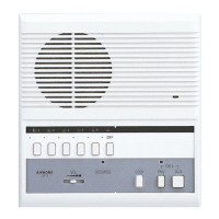
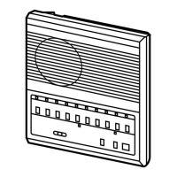
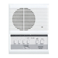
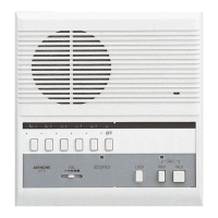
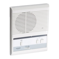
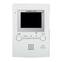
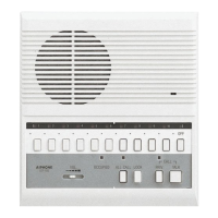
Lists and illustrates available master stations (LEF-3, 5, 10, 10S) and sub stations.

LEF Station Names and Features

Details the names and functions of buttons and indicators for LEF-3 and LEF-5, 10, 10S stations.

Optional System Features

Highlights optional features like All Call & Background Music adapter (BG-10C).

System Features and Capabilities

Master Station Capacity and Features

Details the capacity, door release, and all call transmit capabilities of LEF master stations.

Optional System Enhancements

Describes optional features like All Call, selective door release, horn speakers, and external signaling.

Wiring System Configurations

Explains loop-wired, all-master, single-master, and intermixed system wiring methods.

Wire Reference Chart

Provides wire gauge and conductor counts for standard and selective door release wiring.

Mounting Instructions

Mounting LEF Units to Single-Gang Boxes

Instructions for mounting LEF-3, LEF-5/10/10S master stations and LE room subs.

Wall-Mounting Procedures

Step-by-step guide for removing the operation plate, mounting the chassis, and reassembly.

Desk Mount Terminal Box Installation

Instructions for installing LEW Desktop Terminal Box and connecting it to the LEF master.

Wiring Diagrams and Rules

Sub to Master Station Wiring

Diagrams and rules for wiring LE series subs/door stations to single or multi-master LEF-3 systems.

Master to Master Intercom Wiring

Wiring diagrams for internal communication between LEF-3 master stations.

Master to Sub Station Wiring

Diagrams for wiring LEF-3 masters to LE series subs (LE-A/LE-DA) using parallel or homerun methods.

Door Release and External Signaling Wiring

Door Release Relay Wiring

Wiring diagrams and operation for door release using RY-PA relay with LEF-5 and LE-D/LE-DA stations.

External Signaling and CCTV Relay Wiring

Wiring for external devices like bells or CCTV triggered by station calls, using RY-AC/A relay.

Wiring Terminal Definitions and Controls

LEF Master Station Terminal Connections

Diagrams showing terminal connections for LEF-3, LEF-5/10/10S, and LEW terminal boxes.

Terminal Function Definitions

Detailed explanations of the functions for each terminal (1-10, C, E, R, Y, L, P1-P3, K1-K10).

Call Tone Volume and Mode Adjustment

Instructions for adjusting call tone volume and selecting the call tone mode in occupied status.

All-Master System Configuration and Requirements

All-Master Wiring and Cable Specifications

Details on looped wiring for all-master systems and required cable specifications.

Power Supply and Surge Protection

Information on power supply requirements and recommendations for surge arrestors.

Wiring Diagram: Three LEF-3 with One Door Station

A specific wiring diagram illustrating the connection of three LEF-3 masters to one door station.

Advanced Wiring Diagrams

Wiring Two LEF-3 with Two Door Stations

Wiring diagram for a system with two LEF-3 master stations and two door stations.

Wiring Three LEF-5 with Two Door Stations and Release

Diagram for a system featuring three LEF-5 masters, two door stations, and door release.

Six LEF-5 All-Master System Wiring

Wiring diagram for an all-master system consisting of six LEF-5 stations.

Wiring Configurations with Camera and Signaling

Two LEF-5 with Camera Call-up and Door Release

Wiring diagram for two LEF-5 masters with three door stations, including camera call-up.

Two LEF-5 with Speakers, Release, and Signaling

Wiring for two LEF-5 masters, two door stations, and three speakers with release/signaling.

Wiring for LEF-10S and LEF-10 Systems

LEF-10S with BG-10C and Door Station Wiring

Wiring diagram for an LEF-10S system with BG-10C and one door station.

LEF-10 with Door Stations and Selective Release Wiring

Wiring diagram for an LEF-10 system with nine door stations and selective door release.

Advanced LEF-10S System Wiring

LEF-10S with Subs, Door Stations, and BG-10C

Wiring diagram for a complex LEF-10S system with six indoor subs and two door stations.

System Operation Guide

Making and Receiving Calls

Instructions for calling masters/subs and receiving calls from sub stations or other masters.

Door Answering and Release Operations

Procedures for answering door station calls and using the door release button.

All Call Feature Operation

Guide on using the All Call feature on LEF-10S stations, requiring the BG-10C adapter.

Operation Plate Details and Features

BG-10C, Privacy, and Sub Station Operations

Details on BG-10C adapter, PRIV feature, and LE sub station call/response operations.

Troubleshooting Common LEF System Issues

Single-Master System Troubleshooting

Solutions for problems like no call tone or communication in single-master systems.

Multi-Master System Troubleshooting

Solutions for issues such as masters not calling each other or incorrect call tones.

Advanced Troubleshooting Guide

Multi-Master System Troubleshooting (Continued)

Solutions for remaining multi-master issues including LEDs, door release, All Call, and feedback.

Technical Precautions and Specifications

Important Technical Precautions

Precautions on interference, wiring placement, and proper cleaning procedures for the unit.

LEF System Specifications

Details on power source, communication, wiring distance, dimensions, and weight.

Product Warranty Information

Information regarding the product's warranty period, limitations, and coverage.

Related product manuals