– 6 –
RY-PA
Black Yellow
to CCTV
input
LEF-5 channel's selective gnd. is
K terminal corresponding to the
number terminals.
Contact will be closed
as long as channel #
is selected
to
+
to # channel's selective gnd.
PS12
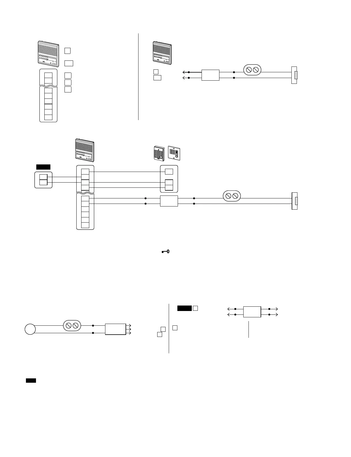
Door release relay wiring, one relay per door station
Operation:
·
To release the door, push the Station Selector button, then press " " to release.
·
When the coil gets 12V DC, the contact changes state, momentarily. Use the relay to trigger a Request-To-Exit
input on any standard access control system, or close an open circuit (shown above).
External Signaling and CCTV relay wiring, one of either relay (or both) per door station
PS12
PS-1225UL, PS-1225S, PS-1225, PS-1215DIN
2
1
K1
L
K2
K3
K4
K5
LEF-5
White lead is 12V DC when
key button is pressed.
Colored lead is ground when
channel is selected.
Brown lead is #1
Red lead is #2
Orange lead is #3
· Relay is activated when
channel is selected and door
release button is pressed.
RY-PA
Black
Yellow
Black wires are a coil. Provide
12V DC to trigger contact.
Contact
Normally Open (N/O) dry contact
1 10 V AC, 1A ,
24V DC, 1A
Door strike
AC T ransforme r
to
L
K#
to channels
LEF-5
1
E
-
+
L
K1
K2
K3
K4
K5
-
+
1
E
-
Door Strike
AC T ransforme r
Yellow Black
LE-D or LE-DA
RY-PA
LEF-5
PS12
Power source
for bell strobe,
horn, etc
RY-AC/A
Contact will close momentarily
when sub station that is wired to channel #
(1, 2, 3, 4, or 5) calls in.
White to #
Black to LEF
-
Red to LEF +
External device
to be triggered
Yellow
·
·
L
terminal 12V DC when door
release button is pressed.
K#
terminal ground when
channel is selected.
K1
is #1
K2
is #2
K3
is #3
Relay is activated when channel is
selected and door release button is
pressed.