EasyManua.ls Logo

Air Lift Load Controller II User Manual

Air Lift Load Controller II
4 pages
To Next Page IconTo Next Page
Page #1 background imageLoading...
Page #1 background image
Customer Service
1-800-248-0892
1
Check Valves
Low Pressure
Sensors
Harness #2
Harness #1
Panel Assembly
Fuse Box
Air Springs
(Previously Installed)
Power Wire
Power Wire
Fuse Adapter
In Line
15 AMP Fuse
Firewall
Grommet
Ground
Compressor
This kit is designed to operate between 5 and 100 p.s.i.
This installation should be done after the Air Spring kit has been installed.
If you have any questions, please call our Technical Service number: 1-800-248-0892.
by
With Low Pressure Sensors P/N 25812
MN-338
(04302)
ECN4031
FIGURE 1
Adapter #1
Adapter #2
Adapter #3 *
Adapter
Fuse
* Uses 3/16 (smaller) Female Push On Connector
INSET A
All pre-assembled gauge
panels have been 100%
leak and function tested.
Do not attempt to tighten,
loosen, or adjust any
fittings and connections.
This will likely cause a leak
or malfunction and void the
warranty.

Other manuals for Air Lift Load Controller II

Question and Answer IconNeed help?

Do you have a question about the Air Lift Load Controller II and is the answer not in the manual?

Air Lift Load Controller II Specifications

General IconGeneral
Control TypeDigital
Pressure GaugeYes
Number of Channels2
CompatibilityUniversal
FeaturesAutomatic leveling
Number of Compressors1
DisplayDigital
Power Supply12V
TypeAir Suspension Control System

Summary

Step-by-Step Installation Guide

Install the Gauge Panel

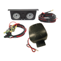
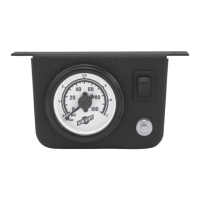
Select a convenient mounting location for the gauge panel and attach it using self-tapping screws.

Install the Compressor Unit

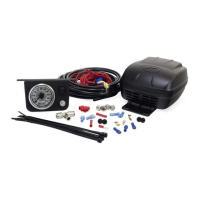
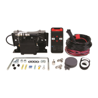
Mount the compressor securely using provided screws, noting frame mounting variations and ground wire connection.

Connect Wiring Harness #1

Connect Harness #1 to the gauge panel and Low Pressure Sensors, matching air lines by color band.

Connect Harness #2 to Compressor

Connect check valves and power wire on Harness #2 to the compressor, hand-tightening connections.

Connect Wiring Harness #2 to Harness #1

Connect the red wire from Harness #2 and banded air lines to the Low Pressure Sensors on Harness #1.

Connect Air Springs and Air Lines

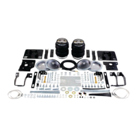
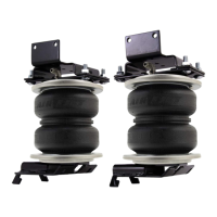
Install T fittings in air lines between air springs and inflation valves, connecting them to Harness #2.

Connect Power Wire to Fuse Box

Route Harness #1 power wire to the fuse box, using an appropriate adapter for vehicle fuse types.

Inflate and Check for Leaks

Inflate air springs to recommended pressure and check all fittings and valves for leaks using soapy water.

Recheck Pressure and Troubleshooting

Recheck pressure after 24 hours and troubleshoot leaks or continuous compressor operation.

Related product manuals