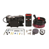
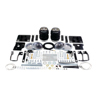
EasyManua.ls Logo

Air Lift Performance 3P User Manual

Air Lift Performance 3P
62 pages
To Next Page IconTo Next Page
Page #1 background imageLoading...
Page #1 background image
Installation Manual
Kit Specific Component List
27697 / 27797
MN-994 • (021602) • ECR 8432
Missing or damaged parts? Call Air Lift Company customer service at (800) 248-0892 for replacement parts.
STOP!
Tank Fittings and Tank Hardware are listed on back of sheet
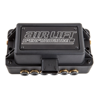
MANIFOLD CONTENT
Item Part # Description ....................................Qty
AE 72614 Manifold ECU 3/8” .................................... 1
AF 20947 Air Line 3/8” ..........................................60 ft.
FILTER CONTENT
Item Part # Description ....................................Qty
AI 11217 P Clamp, 1.5” Cushion ...............................1
AJ 11517 Miniature Filter ............................................1
AK 17173 Screw #14-1/4 x 3/4” Self-Tapping .............1
AL 20937 Hose 1/4” Dia Poly ..................................5 ft.
AM 22677 Tee Fitting - 1/4” FNPT x (2) 1/4” PTC .......1
AN 21048 Pressure-Relief Valve .................................1
HARDWARE CONTENT
Item Part # Description Qty
A 26498-009 Harn – USB Display Cable .........................1
B 26498-006 Harn – Main Harness ..................................1
C 27050 3H/3P Display ...............................................1
D 24503 Fuse ATM 3A ..............................................1
E 24501 Fuse Holder ATM .......................................1
F 24502 Fuse Holder ATO/ATC ...............................1
G 24661 Heat Shrinkable Butt Splice 14-16GA ............1
H 24752 Heat Shrinkable Butt Splice 10-12GA ............3
I 24748 Ring Terminal 3/8” 10-12GA .........................2
J 24524 Ins. Female .187” Term. 14-16GA ................1
K 24594 Ins. Female .250” Term. 14-16GA ................1
Item Part # Description ....................................Qty
L 24561 ATM Fuse Tap Adapter ................................1
M 24542 ATO/ATC Fuse Tap Adapter ........................1
N 10466 Zip Tie 8” Black ...........................................20
O 17103 Screw 5/16”-18 x 1” Zinc...............................2
P 18542 Flat Washer 5/16” Stainless .........................2
Q 17263 Screw 1/4”-14 x 1” Self-Tapping Zinc ...........1
R 17494 Screw 1/4”-14 x 2” Self-Tapping Zinc ...........2
S 10530 Hose Cutter Kit..............................................1
T 24504 FuseLow-ProleMini3A ..............................1
U 24505 Low-ProleMiniFuseTap ............................1
V 24547 Fuse ATO/ATC 30A ....................................1
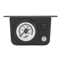
COMPRESSOR
Item Part # Description ....................................Qty
AG 16444 Compressor ................................................1
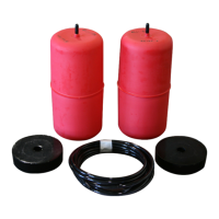
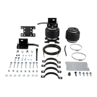
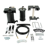
TANK
Item Part # Description ....................................Qty
AH 11955 4 Gallon 5 Port Tank ...................................1
AH 12955 4 Gallon 5 Port Tank (Polished) .................1
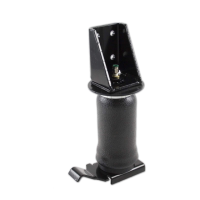
HEIGHT CONTENT
Item Part # Description ....................................Qty
W 34977 HPACK- Height Sensor Linkage .................4
X 26894 Height Sensor Assembly ............................4
Y 26953-012 Harn-12FT RL Height Sensor* ...................1
Z 26953-013 Harn-12FT RR Height Sensor* ...................1
AA 26953-020 Harn-20FT FL Height Sensor* ....................1
Item Part # Description ....................................Qty
AB 26953-021 Harn-20FT FR Height Sensor* ...................1
AC 10466 Zip Tie 8” Black .........................................20
AD 17497 Screw 10-16 x 1 3/4” Self-Tapping Zinc ............ 8
AO 11998 Height Sensor Spacer ......................................... 4
* FL = Front left corner
FR = Front right corner
RL = Rear left corner
RR = Rear right corner
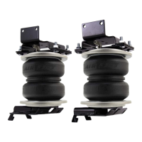
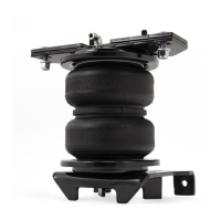
Image may not depict actual kit.

Questions and Answers:

Air Lift Performance 3P Specifications

General IconGeneral
Mobile AppYes
CompressorNot Included
TankNot Included
Product TypeAir Suspension Management System
CompatibilityUniversal
Remote ControlVia Mobile App
Pressure Range0-200 PSI
Power Supply12V
InstallationProfessional Installation Recommended
Preset Management5 Presets
DisplayLCD Screen
Pressure SensorsYes
ManifoldIntegrated Manifold
ConnectivityBluetooth
Control TypePressure-Based

Summary

Hardware Content

Hardware Components List

Lists all hardware components included in the kit for installation and connection.

Manifold Content

Manifold Unit Details

Details the manifold unit and associated air line for the system.

Compressor Content

Compressor Unit Identification

Identifies the compressor unit included in the kit.

Height Content

Height Sensing Components

Details the components related to height sensing for automatic ride height adjustment.

Tank Fittings

Tank Fittings List

Lists various fittings and valves used for the air tank assembly.

Tank Hardware

Tank Installation Hardware

Details the hardware components required for tank installation, such as washers and nuts.

Installation Guide

System Installation Overview

The main guide for installing and setting up the Air Lift Performance 3H/3P system.

Mobile App Integration

App Download and Usage

Instructions for downloading and using the Air Lift Performance mobile app for system control.

Component List

Kit Parts Reference

Lists all parts included in the Air Lift Performance 3H/3P kit for reference.

Introduction

Notation Explanation

Explains hazard notations (Danger, Warning, Caution, Note) used in the manual.

Installation Procedure

Layout Overview

Guidance on planning component placement and routing for optimal system performance.

Installing Air Lift Performance 3H/3P Kit

Layout Overview

Guidance on planning component placement and routing for optimal system performance.

TANK (OPTIONAL)

Tank Pre-assembly

Steps for preparing the air tank by installing fittings and sealant.

FILTER

Filter Mounting

Instructions for mounting the air filter vertically and orienting it correctly.

INSTALL HARNESS

Manifold/relay/compressor connections

Steps for connecting the manifold, relay, and compressor to the main harness.

Display

Route Display Cable

Guidance on routing the display cable to the desired operating location.

INSTALLING AIR LINES

Route and Attach Air Lines

Steps for routing air lines from manifold to air springs, filter, and tank.

MANIFOLD

Manifold Mounting Best Practices

Guidance on locating and mounting the manifold for optimal performance and water prevention.

COMPRESSOR (OPTIONAL)

Compressor Intake Setup

Instructions for attaching the filter to the compressor intake for indoor or outdoor mounting.

HEIGHT SENSORS

Determining Height Sensor Mounting Point

Guidance on selecting a solid mounting point and orienting the sensor for best performance.

SELECTING SENSOR LOCATION

Measure Suspension Travel

Procedure to measure suspension travel at lower and upper limit positions for sensor calibration.

SELECTING SENSOR ARM HOLE

Correlate Suspension Travel to Arm Hole

Guidance on selecting the correct sensor arm hole based on measured suspension travel.

LINKAGE ASSEMBLY/MODIFICATION

Thread Linkage Rod

Ensuring the linkage rod is threaded fully for proper assembly and adjustment.

Installation Diagram

Rear View Diagram

Diagram showing rear view of system component connections for installation.

Installation Diagram

Front View Diagram

Diagram showing front view of system component connections for installation.

HEIGHT SENSORS, CONT.

Cut Rod Linkage

Instructions on measuring and cutting the rod linkage and cover for sensor assembly.

VERIFYING SUSPENSION RANGE

Using Sensor Tools for Verification

Guidance on using tools to confirm height sensor range and adjust as needed.

Troubleshooting Guide

Compressor Issues

Common compressor problems, causes, and solutions like fuse checks and relay replacement.

Permissible Modifications

Extending Height Sensor Harness

Information on ordering extension kits for height sensor harnesses.

Permissible Modifications, Cont.

Rotating 3H/3P Display Keypad

Instructions for rotating the display keypad for horizontal applications.

Display Mounting Template

Display Mounting Dimensions

Template with dimensions for drilling mounting holes for the 3H/3P display unit.

Height Sensor Install Tool

Sensor Alignment Tools

Printable tools for positioning and aligning height sensors during installation.

Manifold Mounting Template

Manifold Mounting Dimensions

Template with dimensions for drilling mounting holes for the manifold unit.

16444 Compressor Mounting Template

Compressor Mounting Hole Pattern

Template detailing the hole pattern for mounting the 16444 compressor.

Notes

User Notes Section

A page designated for user notes or additional remarks.

Limited Warranty and Return Policy

What This Warranty Covers

Details the warranty coverage for Air Lift Performance products.

Replacement Part Information

Obtaining Replacement Parts

Guidance on how to obtain replacement parts and contact Air Lift customer service.

Need Help?

Customer Service Contact

Contact information for Air Lift customer service for assistance.

User Guide Overview

User Guide Introduction

Introduction to the user guide for the Air Lift Performance 3H/3P control system.

Introduction

Important Safety Notices

Key safety warnings and precautions for using the 3H/3P system.

Main Controls

Controller Overview

Overview of the 3H/3P controller's buttons and display elements.

Quick Reference Guide

System Settings Summary

A summary table of system settings, sub-menus, and default values.

Getting Started

Initial System Navigation

Basic steps to navigate the system menus and understand initial setup.

Display Settings

Brightness and Sleep Time

Adjusting display brightness, sleep brightness, and sleep time.

Operation

Rise-on-Start and Preset Maintain

Configuring automatic vehicle leveling and maintaining preset ride heights.

Setup Menu

Sensor Tool (Height Mode)

Using the sensor tool to verify and ensure accurate height sensor range.

Setup Menu, Cont.

Compressor Setup Options

Configuring compressor type, max pressure, duty cycle, and battery voltage.

Calibration Wizard

Initial Setup Questions

Answering questions about vehicle surface, wheel alignment, and manifold mounting.

Calibration, Cont.

Height Sensor Calibration Steps

Calibrating the upper and lower limits for height sensors via auto or manual methods.

Calibration Detail Explained

Auto and Manual Sensor Limits

Explains how auto and manual sensor calibration sets upper and lower height limits.

Calibration Detail Explained, Cont.

Height Calibration Process

Explains the system's actions during height calibration, including movement calibration.

Firmware Updates

Mobile Device App for Updates

Information on downloading the app for firmware, app, and system updates.

Firmware Updates, Cont.

Switching to Landscape Mode

Instructions for changing the controller orientation to landscape mode.

Additional Information

Preset Modes and Operation

Explanation of standard preset modes and how to view, use, and change them.

About Menu

System Information Display

View software versions, serial number, and Bluetooth address for system information.

System Messages

Faults and Problems (Part 1)

Lists system messages related to calibration, manifold orientation, and leaks.

System Messages, Cont.

Sensor and Compressor Messages

Lists messages for sensor limits, compressor freeze, overheat, and pressure issues.

VIAIR Compressor Duty Cycle/Working Pressure

Compressor Ratings and Duty Cycles

Details compressor ratings, duty cycles, and working pressures for various VIAIR models.

Notes

General Notes Section

A page designated for user notes or additional remarks.

Need Help?

Customer Service Assistance

Contact information for Air Lift customer service for assistance.

Related product manuals