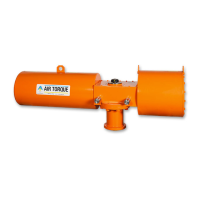
for models AT051U→AT801U (0,5° over 0° for AT045U)
and that the dimension “A” on both sides is the same as
shown in figure 11.
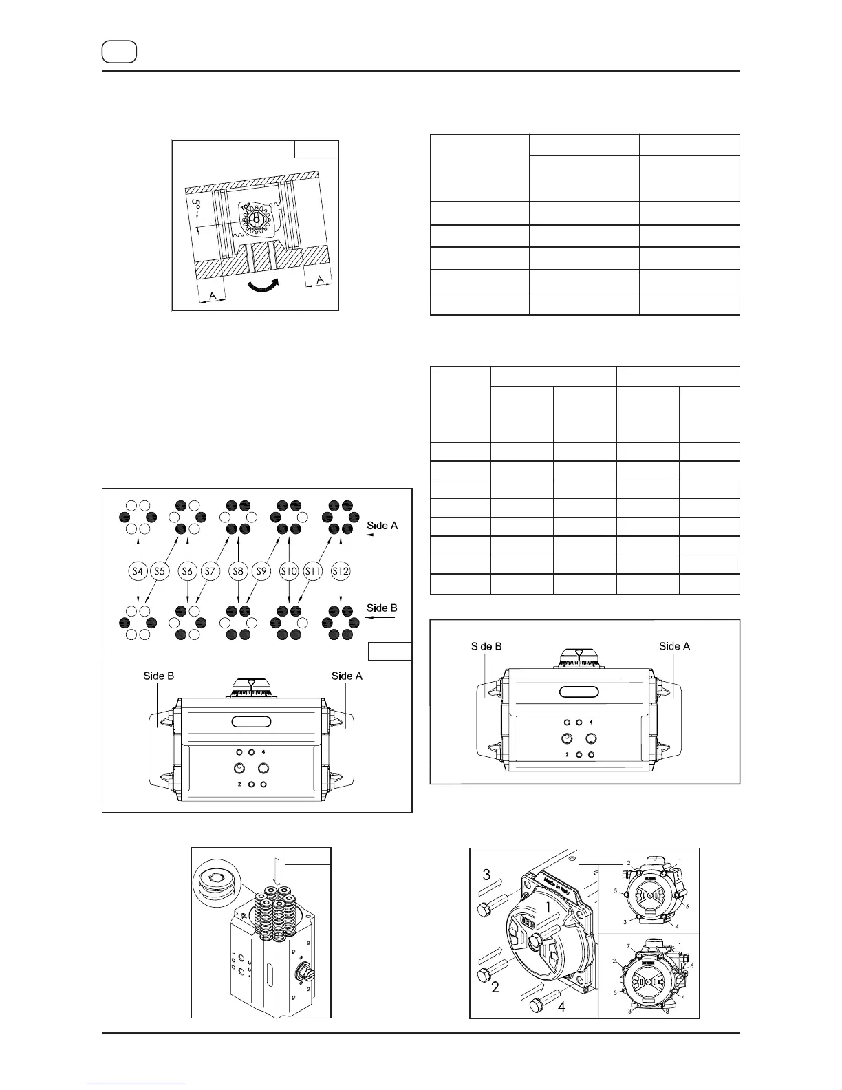
C) End cap (Part N° 30) assembly, figures 12, 13 and 14:
• Assemble one end cap at a time.
• Lubricate the body.
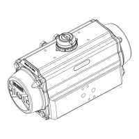
• For spring return actuators, insert the springs in each
end cap according to the desired configuration, as shown
in figure 12 and related tables. For models
AT101U→AT801U insert spring cartridges as shown in
figure 13.
S
PRING SET CONFIGURATION
AT045U configuration:
AT051U configuration:
• Fit end cap o-ring seal (14) into the groove on both end caps.
Fig. 12
Fig. 11
I
MAT 4thGU-E
10
GB
Spring Set
S1-1
S1-2
S2-2
S2-3
S3-3
Side B
AT045U
Spring type
1 (green)
1 (green)
2 (red)
2 (red)
3 (black)
Side A
AT045U
Spring type
1 (green)
2 (red)
2 (red)
3 (black)
3 (black)
Spring
Set
S1
S2
S3
S4
S5
S6
S7
S8
AT051U
Internal
Spring type
1(green)
------------
------------
------------
------------
1 (green)
1 (green)
1 (green)
AT051U
External
Spring type
------------
2 (black)
2 (black)
3 (red)
3 (red)
2 (black)
2 (black)
3 (red)
AT051U
Internal
Spring type
------------
------------
------------
------------
1 (green)
1 (green)
1 (green)
1 (green)
AT051U
External
Spring type
2 (black)
2 (black)
3 (red)
3 (red)
2 (black)
2 (black)
3 (red)
3 (red)
Side B Side A
Fig. 14
Fig. 13
 Loading...