Fig. 06
Fig. 08 Fig. 09
9
I
MAT 4thGU-E
GB
Fig. 10
• Remove top (06) and bottom (07) pinion bearings and top
(20) and bottom (21) pinion o-rings.
• Discard bearings (06) and (07), internal and external thrust
washer (08) and o-rings (20) and (21) if replacing the soft
components.
All the components disassembled and not replaced will
have to be cleaned and inspected for wear and before
reassembly, if necessary, also replace the plugs (09).
6.3) ASSEMBLY:
Prior to assembly, ensure that:
• all the components are perfectly clean and in good
condition.
• the spare parts and the lubricant used are suitable for the
operating temperature of the actuator (see Air Torque
technical data sheets).
• Note: The lubricants suitable for the various operating
temperatures (Standard, HT and LLT actuators) are
available in Air Torque.
Only for “standard” actuators, for temperature from -40°C
(-40°F) to +80°C (+176°F), it is possible to use lubricant
Dow Corning type Molykote
®
G-2003.
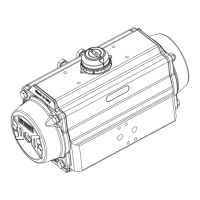
A) Drive shaft assembly (Part N° 60), figures 06, 07
and 07A:
• Install top (06) and
bottom (07) bearings,
grease and insert the
bottom (20) and top
(21) pinion o-rings
onto the shaft.
• Grease the outside
surface of the drive
shaft as shown in figure
06.
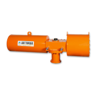
• Insert partially the drive shaft (60) in the body (50),
install octi-cam (01) in the correct position (for standard
assembly or for lock-out) as shown in figures 07 and
07A, related to the bottom and top of the drive shaft and
the rotation of the actuator when energised. Install the
internal thrust bearing (08). Insert completely the drive
shaft in the body.
• Fit external thrust bearing (08), thrust washer (10) and then
external spring clip (18) using snap ring pliers or screwdriver
for spiral rings.
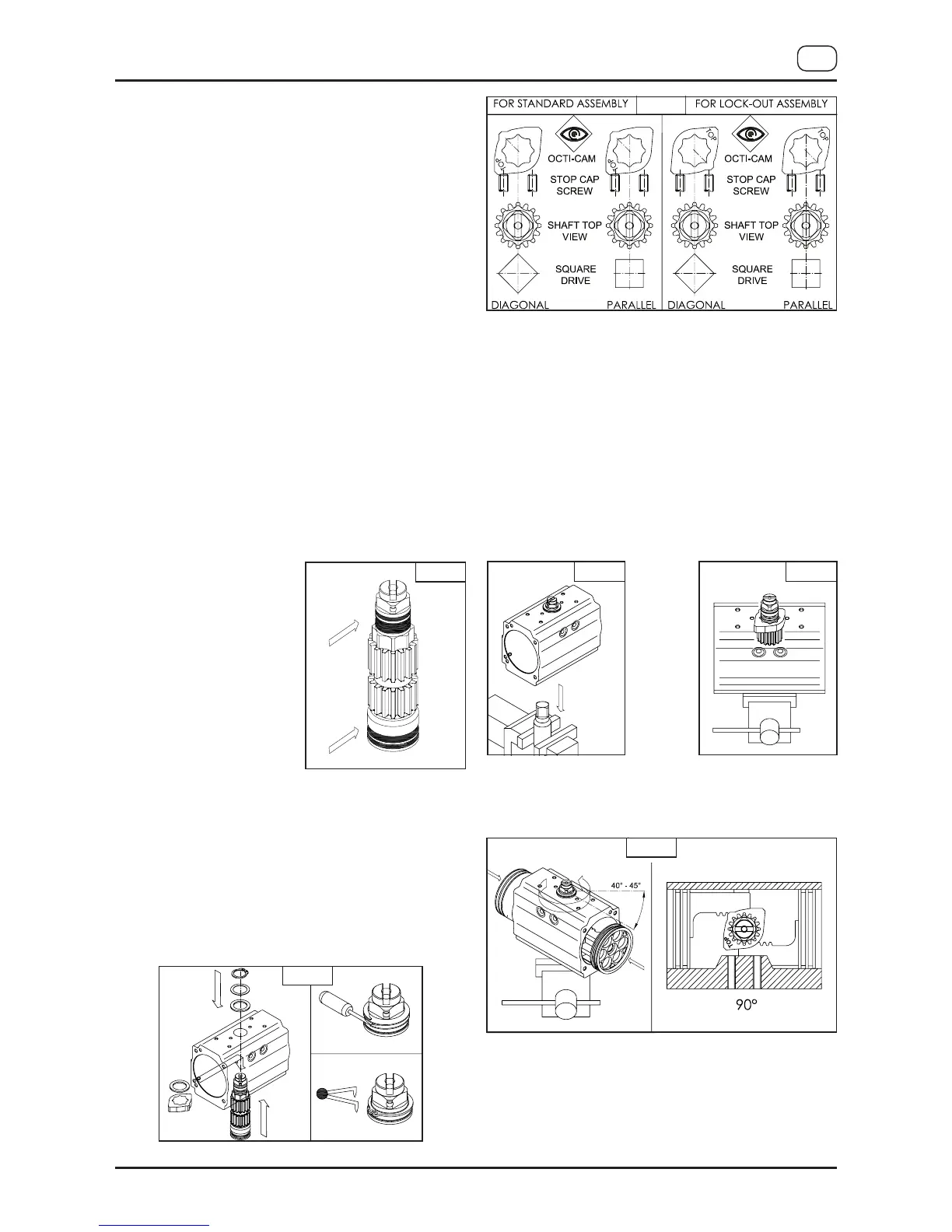
B) Pistons assembly (Part N° 40), figures 08, 09, 10 and 11:
• Grease and install o-rings (16), piston back (05) and
piston head (15) bearings.
• Grease the internal surface of the body (50) and the
piston (40) rack teeth.
• Insert the female connection of the drive shaft (60) in a
properly fixed coupling.
• Ensure that the octi-cam is in the right position as shown
in figure 09.
• For standard rotation assembly type “ST” (clockwise to
close), rotate the body (50) about 40-45° clockwise from
top view, as shown in figure 10.
• Insert and press the two pistons (40) simultaneously
inside the body (50) until the pistons are engaged, then
rotate the body anticlockwise from top view until the
stroke is completed.
• Ensure that with pistons completely closed, the rotation
obtained referred to the axis of the body is about over 0°
F
ig. 07A
Fig. 07
 Loading...