5
• Remove plugs from actuator air connections during
installation and operation. Protect the air connections of
actuators not being used immediately.
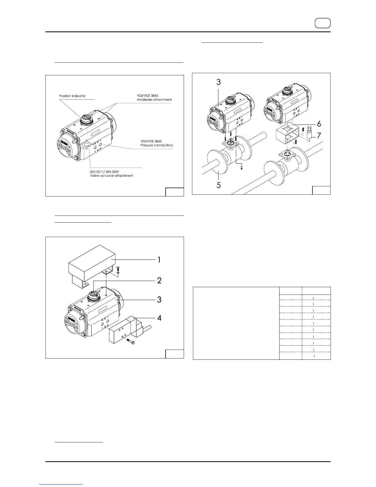
5.2) Interfaces for actuator control and connections, figure A:
5.3) Assembly of accessories: solenoid valves and
switchboxes, figure B:
• Solenoid valve mounting:
Before mounting a solenoid valve, ensure that the
actuator is in its normal position (closed position) with
pistons inwards.
For standard rotation type “ST” (clockwise to close)
assembly: the groove on the drive shaft or on the position
indicator 2 must be horizontal to the longitudinal axis of
the actuator in closed position.
Fit the solenoid valve 4 onto the actuator 3 using the
provided screws (max. tightening torque see table).
• Switchbox mounting:
Fit the switchbox and bracket 1 onto the actuator 3 using
four provided screws (max. tightening torque see table).
5.4) Assembly of valve figure C:
Before proceeding with the assembly of the actuator onto
the valve, be sure that the actuator operates in the desired
direction of rotation when pressurised and both actuator/
valve are in the correct position.
Important: when using a spring return actuator for a fail
safe operation, ensure that when air or electricity failure
occurs the direction of rotation is correct for your application.
Fit the actuator 3 onto the valve 5. It is possible to assemble
the valve onto the actuator in two ways:
• Direct-mount: fit the stem of the valve 5 directly into the
female connection of the actuator 3 and bolt together
through the valve ISO pad (max. tightening torque see table).
• Bracket-mount: mounting with a bracket 6 and coupling
7, the bracket is bolted to the actuator / valve to join
them together and the coupling is used to connect the
actuator output drive to the valve stem (max. tightening
torque see table).
6) MAINTENANCE INSTRUCTION
With the information given below, AIR TORQUE provides
the end user with all the required information necessary
for maintenance. Under normal conditions, the actuator
requires only periodic observation to ensure proper operation.
Maintenance (disassembly, maintenance and rebuilding)
of AIR TORQUE actuators is allowed only to AIR TORQUE
personnel or properly instructed personnel. In case of
controversy the product guarantee will expire!
Spare kits for maintenace are available to replace all
seals and bearings (soft parts indicated into the table),
that may be necessary between 300.000 and 1.000.000
cycles depending on operating and environmental
conditions and actuator size.
I
MAT 4thGU-E
GB
Fig. A
Fig. B
Fig. C
 Loading...