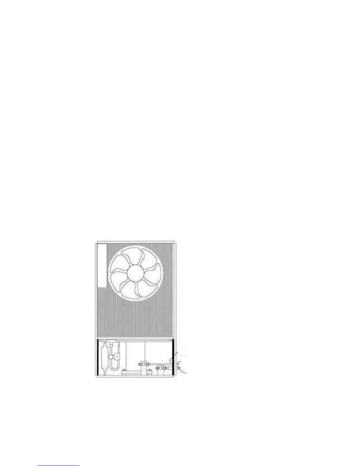
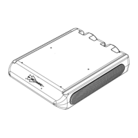
DETAILS FOR RH, LH & REAR PIPE ENTRY
RIGHT HAND ENTRY
Figure X
Cut out hole in blanking caps and fit to form a seal
9.5ø tube with insulation
6.4ø tube
Pass power and control cables out with this tube
PIPE INSTALLATION & CONTROL WIRING
(See also Tips on Flaring, page 11)
All pipe work must be clean and dry refrigeration grade annealed copper tube.
The pipe work consists of a 6.4mm dia. tube (liquid line), and a 9.5mm dia. tube
(return gas) running between the Con/set and the A/H.
These tube sizes are equivalent to 1/4” and 3/8” respectively.
The 9.5 dia. must be insulated with 10 x 10 foam rubber insulation.
Entry to the Con/set (Refer figures x, y & z). Retain the red plastic blanking
caps on the pipes before flaring. These can be reinserted after the pipework is
tightened up. It is essential that a good airseal is made here. Failure to do so will
result in hot air being possibly leaked into the conditioned space.
The control cable and A/H power cable are passed out with the 6.4 dia. pipe, and
usually runs to the A/H taped to the pipe.
Now refer to the A/H installation, after which we will return to the Con/set to
open up the refrigeration circuit, and fit the exterior louvre panel.
4