Use and maintenance manual Self-propelled aerial platforms Page 9
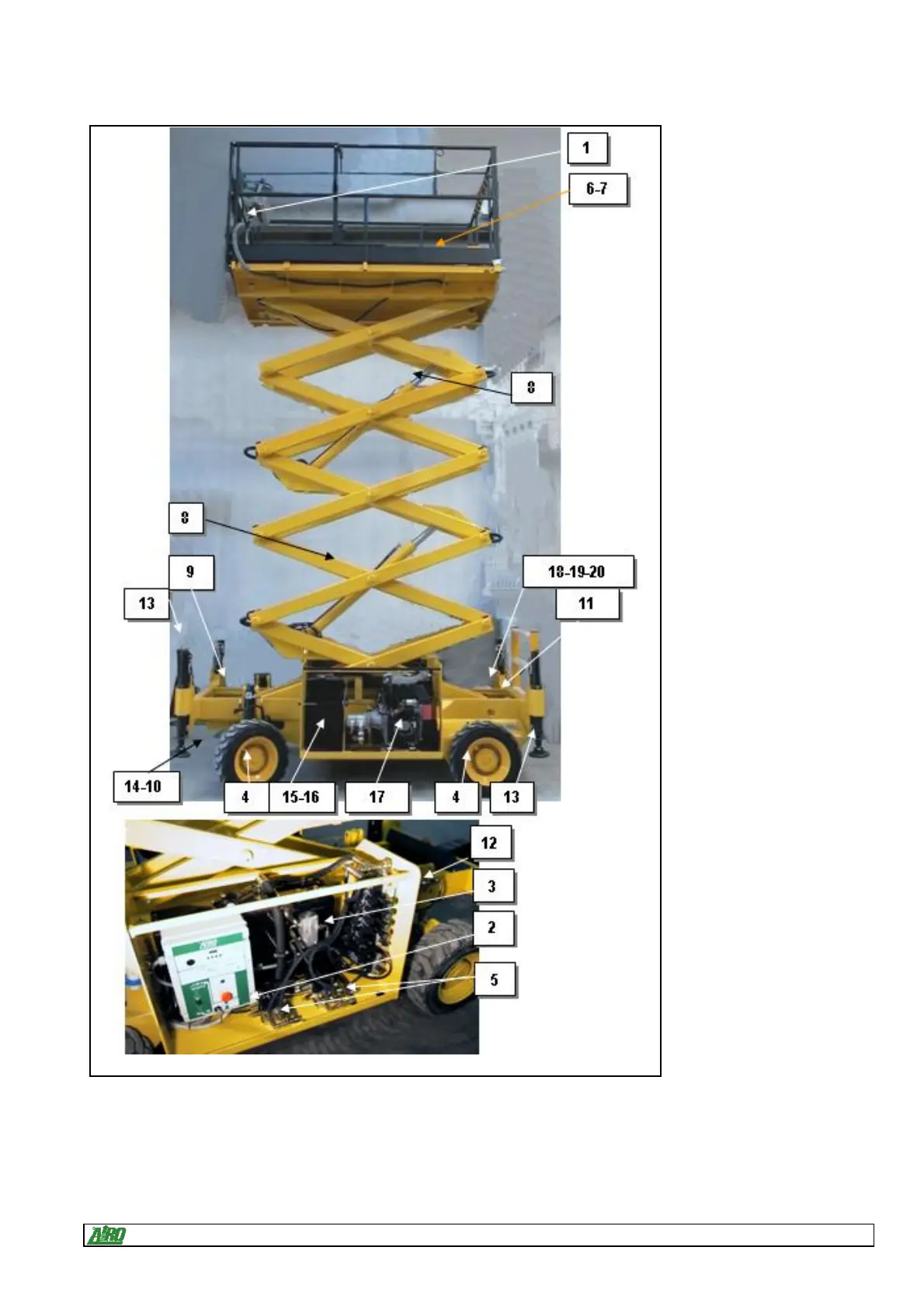
1.7 Location of main components
Below is a diagram showing
the machine and its
components.
1) Control panel;
2) Electric control unit;
3) Hydraulic control unit;
4) Hydraulic drive motors;
5) Traction control hydraulic unit
(traction plate);
6) 220V socket;
7) Bubble level for visual check
of machine levelling;
8) Lifting cylinders;
9) Battery;
10) Power steering;
11) Inclinometer;
12) Emergency manual pump;
13) Levelling cylinders;
14) Oscillating axle;
15) Fuel tank;
16) LPG cylinder (models "-B/G");
17) Heat engine;
18) Microswitch M1;
19) Microswitch M1S;
20) Microswitch M3 (optional).
Fig.2