6408 216th Street SW | Mountlake Terrace, WA 98043 USA
T +1.425.778.7728 F +1.425.778.7727 | www.SymetrixAudio.com
14
User’s Guide
Bypass and Analog Control Inputs
Bypass
The 6200 has two bypass modes - software (DSP) and hardware (relay).
The DSP (SW) bypass can be invoked a number of ways. The hardware
(HW) bypass is only accessible via contact closure wired to a rear panel
euroblock connector.
DSP (SW) BYPASS:
DSP (SW) Bypass mode can be invoked by several means:
1. Pressing the BYPASS button on the front of the 6200 while in one of the top-
level menus (Home, In LVL or Out LVL).
2. Pressing the BYPASS (PROGRAM 0) button on an attached RC-1 remote.
3. Pressing the DSP Bypass button in an attached (and currently “online”) 6200
Designer GUI.
4. Activating a contact closure attached to the SW and Ground terminals of the
rear panel REMOTE BYPASS connector.
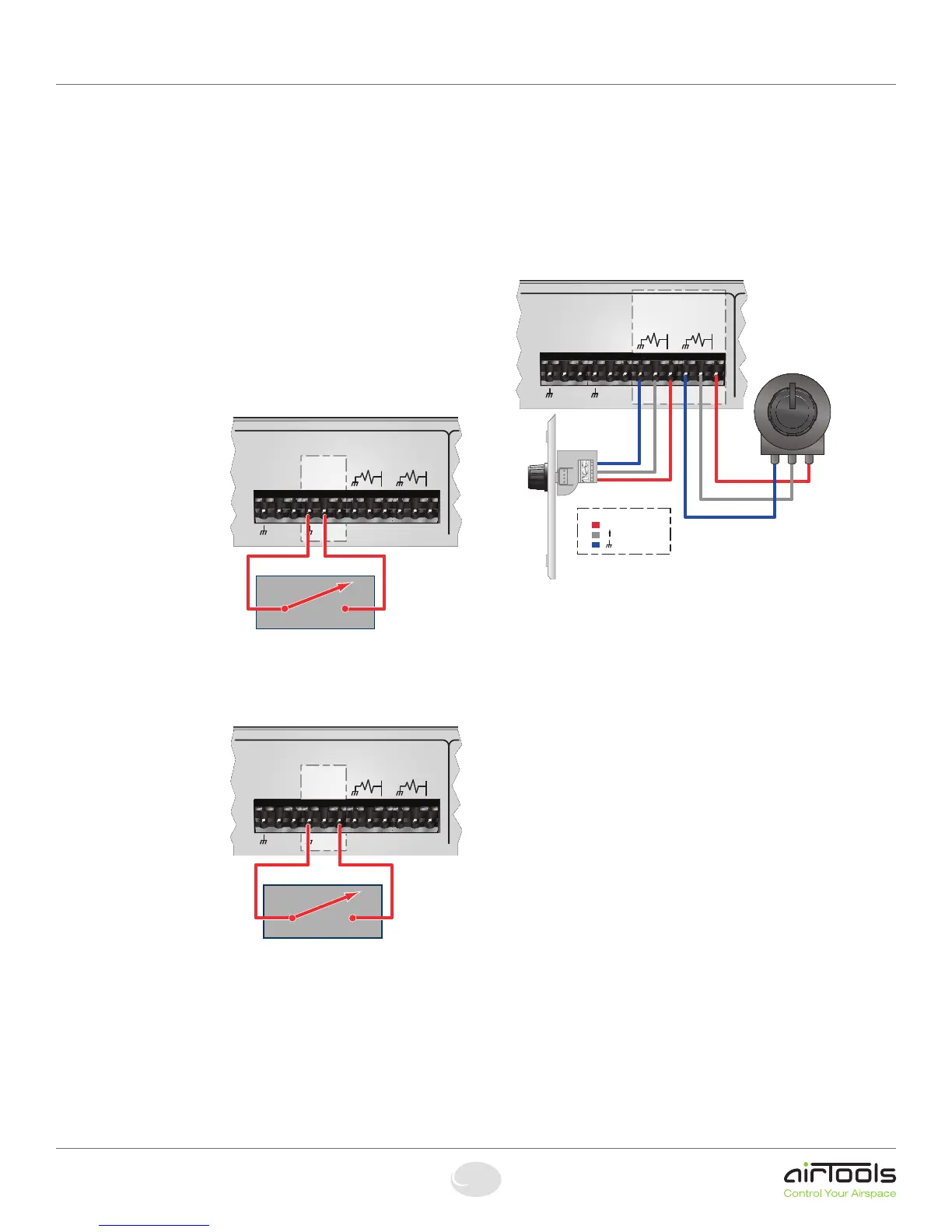
DSP (SW) Bypass
switch wiring:
The figure right shows the
connection of a contact
closure to the SW Bypass
function of the REMOTE
BYPASS connector.
NOTE: A latching switch
should be used in order to
hold the bypass state.
NOTE 2: The switch on the
REMOTE BYPASS connector
will both override and inter-
rupt the bypass state set by methods 1 through 3 listed above.
HARDWARE MUTE (HM):
Hardware Mute (HM) isn’t
a true “bypass” or “mute”
but actually a relay-activated
output disconnect. It is only
accessible by activating a
contact closure attached to
the HM and Ground terminals
of the rear panel REMOTE
BYPASS connector.
Hardware Mute (HM) switch
wiring:
The figure right shows the
connection of a contact
closure to the Hardware Mute
function of the REMOTE BYPASS connector.
NOTE: A latching switch should be used in order to hold the bypass state.
NOTE 2: Activating the Hardware Mute function invokes relays which
completely disconnect all active circuitry from their associated
output connections.
NOTE 3: Hardware Mute is automatically engaged upon loss of power.
Analog Control Inputs
The 6200 features two analog control inputs which provide real-time
control of up to two parameters per port using standard 10k Ohm linear
potentiometers. The figure right shows the connections.
Calibrating an Analog Control Input
Once you have wired up your pot to an analog control input, it should be
calibrated to ensure the full travel of the pot is read correctly by the 6200.
1. Press the HOME button to ensure we are starting from the top.
2. Press the NEXT button once.
3. The display should read “Section to Edit, - Channel 1 Menu -”.
4. Turn the ADJUST knob clockwise until the menu reads “Section to Edit, -
Setup Menu -”.
5. Press the NEXT button once.
6. Turn the ADJUST knob clockwise until the menu reads “- Setup Menu -,
-- External Controls --”.
7. Press the NEXT button once and the menu should read “Lowest Cntrlr Level,
ADC1: xxx Min: 000”. This menu is showing you the current pot position
“ADC: xxx” and the current minimum calibration setting “Min: xxx”.
8. Turn your pot fully counter-clockwise and then turn the ADJUST knob so that
the “Min: xxx” value is equal to the displayed “ADC: xxx” value.
9. Press the NEXT button once and the menu should read “Highest Cntrlr Level,
ADC1: xxx Max: 255”. This menu is showing you the current pot position
“ADC: xxx” and the current maximum calibration setting “Max: xxx”.
10. Turn your pot fully clockwise and then turn the ADJUST konb so that the
“Max: xxx” value is equal to the displayed “ADC: xxx” value.
NOTE: The above steps assume you are calibrating ADC1 (Analog Control
Input 1). Follow the same steps to calibrate ADC2 (Analog Control Input 2)
substituting ADC2’s menus where appropriate.
Assigning a Parameter to an Analog Control Input
Assignment of parameters to an Analog Control Input is done within 6200
Designer. Refer to the online help module within 6200 Designer for more
information.
RS-485
AB
REMOTE
BYPASS
HMSW
ANALOG
CONTROL
INPUT 2
ANALOG
CONTROL
INPUT 1
POTENTIOMETER
3.3V
OUT
3.3V
OUT
Potentiometer
Symetrix
RC-3
=
= + 3.3V (Clockwise)
= (Counter Clockwise)
Legend:
ANALOG
CONTROL
INPUT 2
RS-485
ANALOG
CONTROL
INPUT 1
POTENTIOMETER
AB
3.3V
OUT
3.3V
OUT
REMOTE
BYPASS
HMSW
External switch or relay contact
ANALOG
CONTROL
INPUT 2
RS-485
ANALOG
CONTROL
INPUT 1
POTENTIOMETER
AB
3.3V
OUT
3.3V
OUT
REMOTE
BYPASS
HMSW
External switch or relay contact