6408 216th Street SW | Mountlake Terrace, WA 98043 USA
T +1.425.778.7728 F +1.425.778.7727 | www.SymetrixAudio.com
8
User’s Guide
Basic Setup
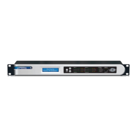
POWER: Connect the
IEC connector side of the
supplied AC cord to the
receptacle on the rear of the
6200. Connect the other
side of the AC cable to an
AC power source that is
of the correct voltage and
frequency (100-240 VAC,
50-60 Hz). Use only the
power cord and connector
specified for the product and
your operating locale.
ANALOG IN: Using a standard microphone cable terminated with one
maleXLRconnectorandonefemaleXLRconnector,connectthemale
endintotheCHAN1-ANALOGINofthe6200andthefemaleendinto
your microphone.
Caution 1: When Phantom Power is engaged, do not use
unbalanced microphones or mic cables.
Caution 2: When Phantom Power is engaged, do not use
switchedmicswhichshortpin2and/orpin3toground.
Caution 3: When Phantom Power is engaged, always turn
down monitors/headphones before connecting or disconnecting
microphones.
ANALOG OUT: Using a standard mic/line cable terminated with one
maleXLRconnectorandonefemaleXLRconnector,connectthe
femaleendintotheCHAN1-ANALOGOUTofthe6200andthemale
end into your destination device. These outputs are +4 dBu balanced
line level outputs. If you need an unbalanced output, see the analog
audio wiring diagrams on the previous page.
NOTE: Wiring the outputs to an unbalanced cable will typically result in
an output level that is 6 dB lower than the output level achieved using a
balanced cable.
PHANTOM POWER (if required - skip this section if using a
dynamic mic which does not require phantom power): All condenser
microphones require some kind of electrical power. This power may
be supplied by internal batteries, an external power supply that is
connected to the microphone by a special multiwire cable, or through a
standard microphone cable by “phantom” or “T system” powering.
Phantom powering and T system powering are incompatible systems.
Phantom power derives its name from its invisibility to audio signals,
even though the microphone cable carries both phantom power (as
direct current) and audio signals (as alternating current). Specifically,
the term phantom power means a positive DC voltage sent to the
microphone on both audio leads, through current-limiting resistors
which also serve to isolate the audio leads from one another. Enabling
phantompowerappliesphantompowerviapins2and3ofthemic
inputXLRconnectors.
The phantom power technique uses the two signal conductors in a
standard balanced mic cable to deliver the power required by the
microphone, eliminating the need for internal batteries or an external
power supply. Because the voltage is applied equally to both sides of
a floating balanced circuit, no current flows through the microphone’s
transformer, or through the microphone element itself.
It is often said that the sound of some dynamic microphones is affected
by phantom power and that ribbon mics cannot be plugged into an
input that is phantom powered. For the most part, these are myths that
grew out of difficulties created by other problems in the mic circuit:
1.WhenXLRconnectorsarematedthereisnoguaranteethatboth
pins2and3willmakecontactatexactlythesametime.Itispossible
that a damaging current could flow through the mic for a brief moment
under these conditions. However, this is a connector problem, not a
problem with the mic itself or phantom power in general.
2. In the past, it was a common practice to ground the center tap of
the mic’s output transformer. However, this practice should be avoided
in phantom powered systems. The solution: Locate the center tap and
cuttheconnectionbetweenitandpin1oftheXLRconnector.
3.Ifthemic’soutputtransformerhasdevelopedleakage,the
microphone may become noisy when phantom power is turned on.
Crackling, sputtering or even humming noises may occur. The leakage,
not the power, is the problem. The solutions are:
A. Turn off the phantom power.
B. Put a 1:1 low-impedance transformer between the mic and the input.
C. Get the mic repaired.
Basic Setup
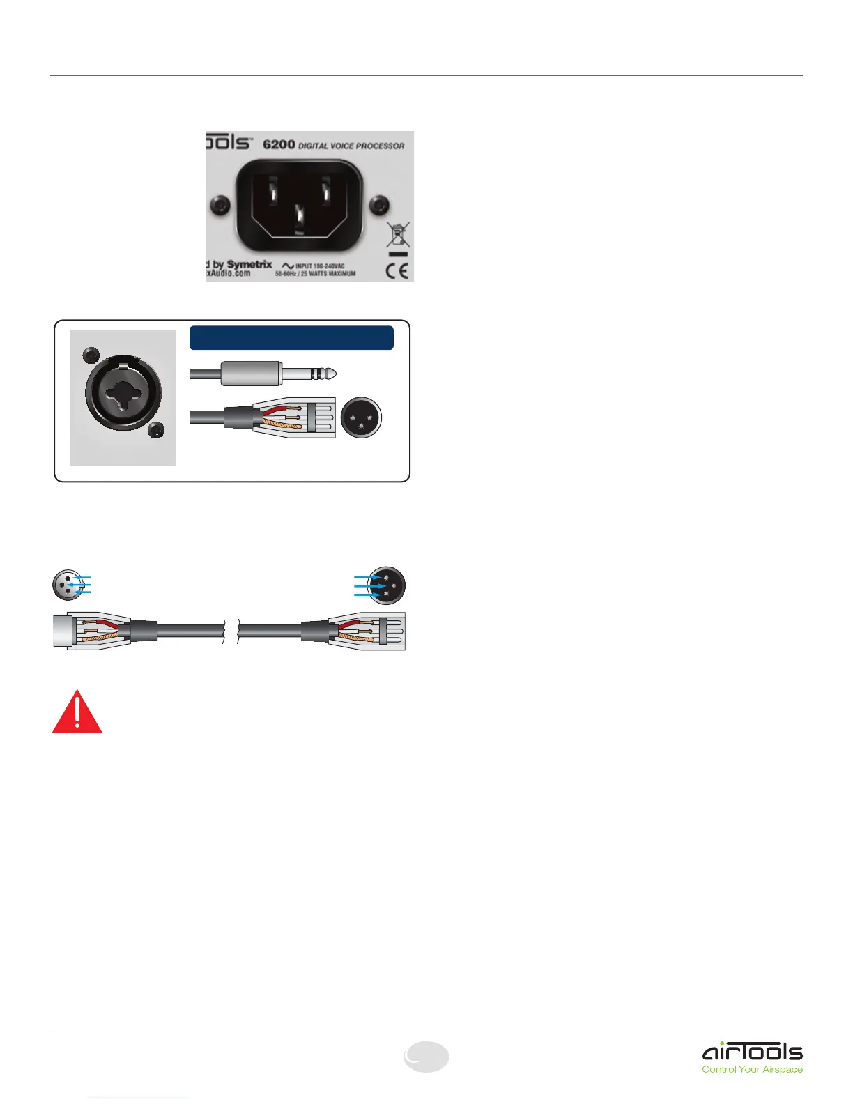
The 6200 Input Connector
ANALOG IN
CHANNEL 1
This multi-purpose connector is both a
Female XLR connector and a TRS Jack.
Pin 2 = (+) Plus
Pin 3 = (–) Minus
Pin 1 = Ground
Originating Device Output Destination Device Input
Pin 2
Pin 3
Pin 1
Pin 2
Pin 3
Pin 1
Pin 2 = (+) Plus
Pin 3 = (–) Minus
Pin 1 = Ground
 Loading...