6408 216th Street SW | Mountlake Terrace, WA 98043 USA
T +1.425.778.7728 F +1.425.778.7727 | www.SymetrixAudio.com
4
User’s Guide
Introduction
Introduction
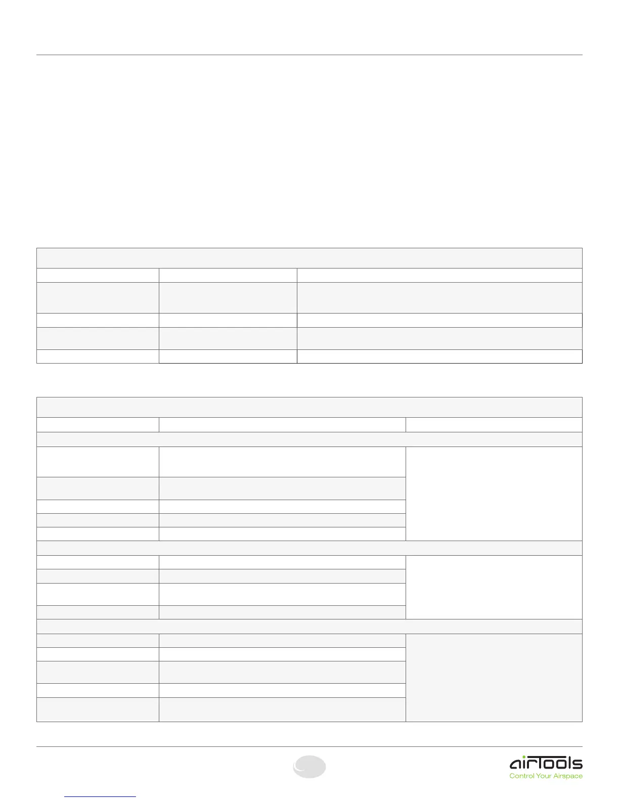
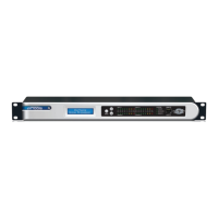
The AirTools 6200 Digital Voice Processor is designed to meet the increas-
ingly sophisticated needs of broadcasters operating in both analog and
digital realms featuring an optimum mix of signal processing modules
and control features. The modules include: highpass, lowpass, and
shelving filters, de-esser, downward expander, comp-limiter/AGC-leveler,
4-band parametric EQ and voice symmetry. The 6200 is a dual-channel
unit with two discrete audio pathways capable of processing microphone
or line-level sources, independently or as a stereo pair with a 24-bit/48
kHz digital signal path. Creation of voice programs and signal process-
ing parameters may be done from the 6200 front panel or from 6200
Designer, a Windows
®
application
(provided). From a PC, the 6200 may be controlled via RS-232, USB or
Ethernet. In lieu of computer control, real time changes of program and
DSP parameters may be actuated via user supplied ESE time code, pots,
encoders, switches, or MIDI devices.
Mechanical Data
ITEM DESCRIPTION DETAILS
Space Required 1U(WDH:48.26cmx26.6cmx4.369
cm/19inx10.475inx1.72in).Depth
does not include connector allowance.
Allow at least 1 inch additional clearance for rear panel connections. Additional depth may
be required depending upon your specific wiring and connections.
Electrical
100-240 VAC, 50-60 Hz, 25 Watts maximum. No line voltage switching required.
Ventilation Maximumrecommendedambientoper-
atingtemperatureis30C/86F.
Ventilation should not be impeded by covering the unit with items such as newspapers,
tablecloths, curtains, etc.
Weight
4.45 kg / 9.82 lbs.
Performance Data
Item DESCRIPTION DETAILS
INPUTS:
Nominal Input Level Analog:+4dBuor-10dBVlinelevel,-36dBuor-56dBumiclevel(software
selectable) with 20 dB of headroom
Digital: -20 dBFS: 100-240 VAC, 50-60 Hz, 25 Watts maximum.
NOTE:Forunbalancedanaloginput,eitherreference
the minus input terminal to the signal source ground
(pre ferred) or ground the minus input to the adjacent
ground terminal (tie low to ground). Using the second
method deprives you of the common mode rejection
inher ent in a balanced input, even when coming from
an unbalanced source.
Maximum Input Level Analog: +24 dBu
Digital: 0 dBFS
Input Impedance Analog: 20k Ohms, Digital: 110 Ohms, +/- 10
CMRR > 50 dB (0 dBu, 20 Hz to 20 kHz)
Analog to Digital Conversion 24-bit delta/sigma
OUTPUTS:
Nominal Output Level Analog: +4 dBu line level with 20 dB of headroom, Digital: -20 dBFS NOTE:Forunbalancedanalogoutput,float(donot
connect) the minus output terminal. Unbalanced usage
results in 6 dB lower output level.
Maximum Output Level Analog: +24 dBu, Digital: 0 dBFS
Output Impedance Analog: 200 Ohms balanced, 100 Ohms unbalanced, Digital: 110 Ohms,
+/- 10%
Digital to Analog Conversion 24-bit delta/sigma
SYSTEM
Nominal Sample Rate 48kHz
Sample Sync Range 48kHz+/-100ppm
Dynamic Range Analog: > 114 dB (20 Hz to 20 kHz, A-weighted), Digital: 144 dB typical,
unweighted
Frequency Response Analog: 20 Hz - 20 kHz, Digital: 20 Hz - 24 kHz
THD + Noise AnalogIn-to-Out:0.0035%(20Hzto20kHz,unweightedwith+24dBu
output)DigitalIn-to-Out:>117dB@1kHz