Do you have a question about the Airwell DS Ducted Series and is the answer not in the manual?
Procedure for examining the unit upon receipt for transit damage.
Precautions to take when lifting the unit to avoid damage.
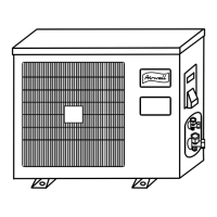
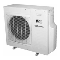
Guidelines for selecting the optimal installation location for outdoor units.
Procedures and requirements for condensate drainage from indoor and outdoor units.
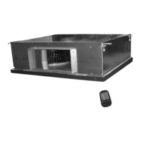
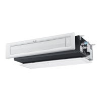
Requirements for duct design and heat load calculations.
Considerations for fitting fresh air intakes to ducted systems.
Requirements for air filter provision and sizing in ducted systems.
Guidelines for connecting, sizing, and handling refrigerant lines.
Procedure for testing the refrigeration system for leaks using pressure.
Process for evacuating the system to remove moisture and contaminants.
Steps for charging the refrigeration system with refrigerant.
Requirements for safe and compliant electrical installation.
Essential factors for reliable and efficient unit operation.
Information regarding the unit's warranty terms and conditions.
Method for selecting appropriate supply cable sizes for safe operation.
Diagrams and instructions for wiring connections for different unit types.
Details on pipe sizes, cable sizes, and wiring for various unit models.
A checklist of essential items to verify before starting the unit.
Procedures for checking unit operation after installation.
Checking for unusual noises or vibration in running components.
Verifying electrical connections and voltage at unit terminals.
Final inspection of installation and refrigeration connections.
Guidance on instructing the customer on unit usage and maintenance.
How to remove access panels for maintenance.
Instructions for cleaning or replacing air filters.
Checking the condition of indoor fan drive components.
Instructions for inspecting and cleaning the outdoor coil.
Inspection of electrical components like relays and contactors.
Recommended checks for the sealed refrigeration system.
A comprehensive list of maintenance tasks for the unit.
Description and function of each button on the RC4 remote control.
Explanation of the different operating modes and features of the RC4 remote.
Guide to configuring the RC4 remote control using DIP switches.
Explanation of the various indicator lights on the unit.
Description of manual buttons for mode selection and filter reset.
The location on the unit that receives remote control signals.
Manual operation button for Cooling, Heating, or Off.
Used for dirty filter reset, PCB reset, or buzzer control.
Terminals for remote ON/OFF control via time clock or sensors.
Describes the Red Flashing LED symptom indicating a potential issue.
Step-by-step guide to activate and use the self-diagnostic mode.
Table correlating LED flashes to specific fault conditions.
Explains causes for intermittent flashing of the red LED.
Table showing resistance values for thermistors at different temperatures.
Table showing DC voltage readings for thermistors under various conditions.
Instructions for enabling the self-test mode on the unit.
Verifies unit model via LED display during self-test.
Tests the functionality of unit LEDs and internal relays.
Tests the timing of relay activation for zero crossing.
Tests thermistors, level switches, and clock terminals.
Checks the CPU rise time after power interruption.
Verifies the functionality of the unit's memory.
Lists part numbers for model plugs for different unit types.
Diagrams showing jumper configurations for various unit types.
Describes indoor fan speed control based on indoor coil temperature in heating.
Explains how high outdoor coil temperature affects cooling operation.
Explains how high indoor coil temperature affects heating operation.
Describes how low indoor coil temperature affects cooling operation.
Details the process of defrosting the outdoor coil in heating mode.
Explains the conditions for starting and ending the de-ice cycle.
Information on infrared receivers and optional accessories for ducted units.
Information on the Surestart 6 softstarter for specific models.
Explanation of the fault indication LEDs on the softstarter.
Important notes regarding softstarter installation and function.
| Type | Ducted |
|---|---|
| Refrigerant | R410A |
| Power Supply | 220-240V, 50Hz |
| Operating Temperature (Cooling) | 18°C to 43°C |
| Operating Temperature (Heating) | -7°C to 24°C |
| Air Flow (Indoor Unit) | 850 m³/h |
| Dimensions (Indoor Unit) | Varies by model |
| Dimensions (Outdoor Unit) | Varies by model |
| Weight (Indoor Unit) | Varies by model |
| Weight (Outdoor Unit) | Varies by model |