13
E. Additional refrigerant charging
Charge the additional refrigerant as liquid state with the gauge.
If the additional refrigerant can not be charged totally when the outdoor stops, charge it at the trial mode.
If the unit runs for a long period in the state of lack of refrigerant, compressor will occur failure.
(the charging must be nished within 30 minutes especially when the unit is running, menawhile charging the refrigerant).
A. Charging amount when out of factory excludes the refrigerant in the pipe.
B. The unit only is charged the standard volume of refrigerant (distributing pipe length is 0m).
Additional charging amount=actual length of liquid pipe x additional amount per meter liquid pipe
Additional charging amount=L1×0.35+L2×0.25+L3×0.17+L4×0.11+L5×0.054+L6×0.022
L1: total length of 22.22 liquid pipe L2: total length of 19.05 liquid pipe L3: total length of 15.88 liquid pipe
L4: total length of 12.7 liquid pipe L5: total length of 9.52 liquid pipe L6: total length of 6.35 liquid pipe
C. Refrigerant charging and additional charging
Note:
• To prevent the different oil into the pipe, please use the special tool for R410A, especially for gauge manifold and
charging hose.
• Mark the refrigerant type in different colour on the tank. R410A is pink.
• Must not use the charging cylinder, because the R410A will change when transferring to the cylinder.
• When charging refrigerant, the refrigerant should be taken out from the tank as liquid state.
• Mark the counted refrigerant volume due to the distributing pipe length on the label.
Tighten torque as the table below:
Tighten torque N.m
Shaft (valve body) Cap (cover) T-shape nut (check joint)
For gas pipe Less than 7 Less than 30 13
For liquid pipe 7.85 (MAX15.7) 29.4 (MAX39.2) 8.8 (MAX14.7)
Installation instruction
Additonal refrigerant charging per meter(kg/m)
Charge when out of factory
Model Ø22.22 Ø19.05 Ø15.88 Ø12.7 Ø9.52 Ø6.35
0.35 0.25 0.17 0.11 0.054 0.022 Refer to label
GWP: 2088
The product contains uorinated greenhouse gases and its functioning relies upon such gases.
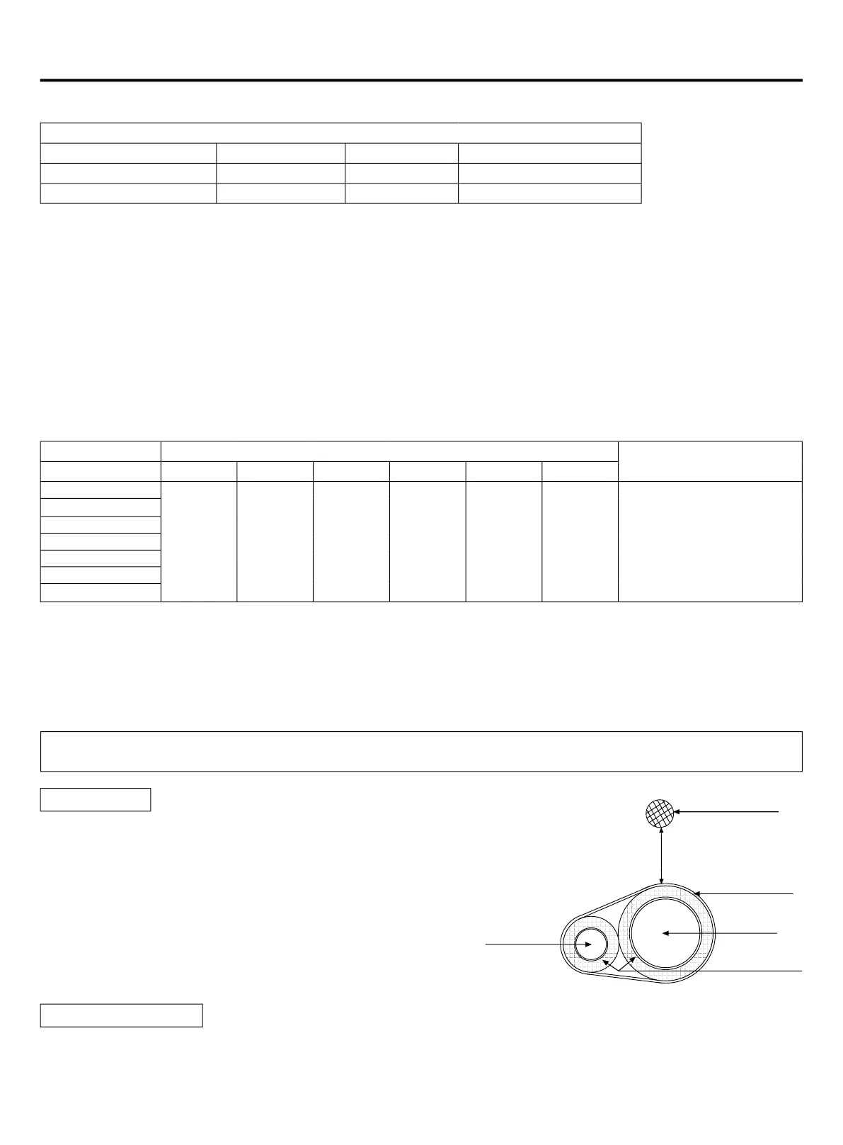
• Gas pipe and liquid pipe should be heat insulated separately.
• The material for gas pipe should endure the high temperature
over 120°C.That for liquid pipe should be over 70°C.
• The material thickness should be over 10mm, when ambient
temp. is 30°C, and the relative humidity is over 80%, the material
thickness should be over 15mm.
• He material should cling the pipe closely without gap, then be
wrapped with adhesive tape. The connection wire can not be put
together with the heat insulation material and should be far at
least 20cm.
Heat insulation
• In operation, the pipe will vibrate and expand or shrink. If not being xed, the refrigerant will focus on one part to cause
the broken pipe.
• To prevent the central stress, x the pipe for every 2-3m.
Fix the refrigerant pipe
Connection wire
over 20cm
Adhesive tape
Gas pipe
Heat insulator
Liquid pipe
AWAU-YCV080-H11
AWAU-YCV150-H13
AWAU-YCV150-H11
AWAU-YCV180-H13
 Loading...