12a-38
CONTROL SYSTEM
Revision 0
12A.20. System diagnostics
Pressing Mode button for 5-10 seconds in SB or any other operation mode will activate
diagnostic mode by the acknowledgment of 3 short beeps and lighting of COOL and HEAT LEDs.
In diagnostic mode, system problems will be indicated by blinking of Heat & Cool LEDs.
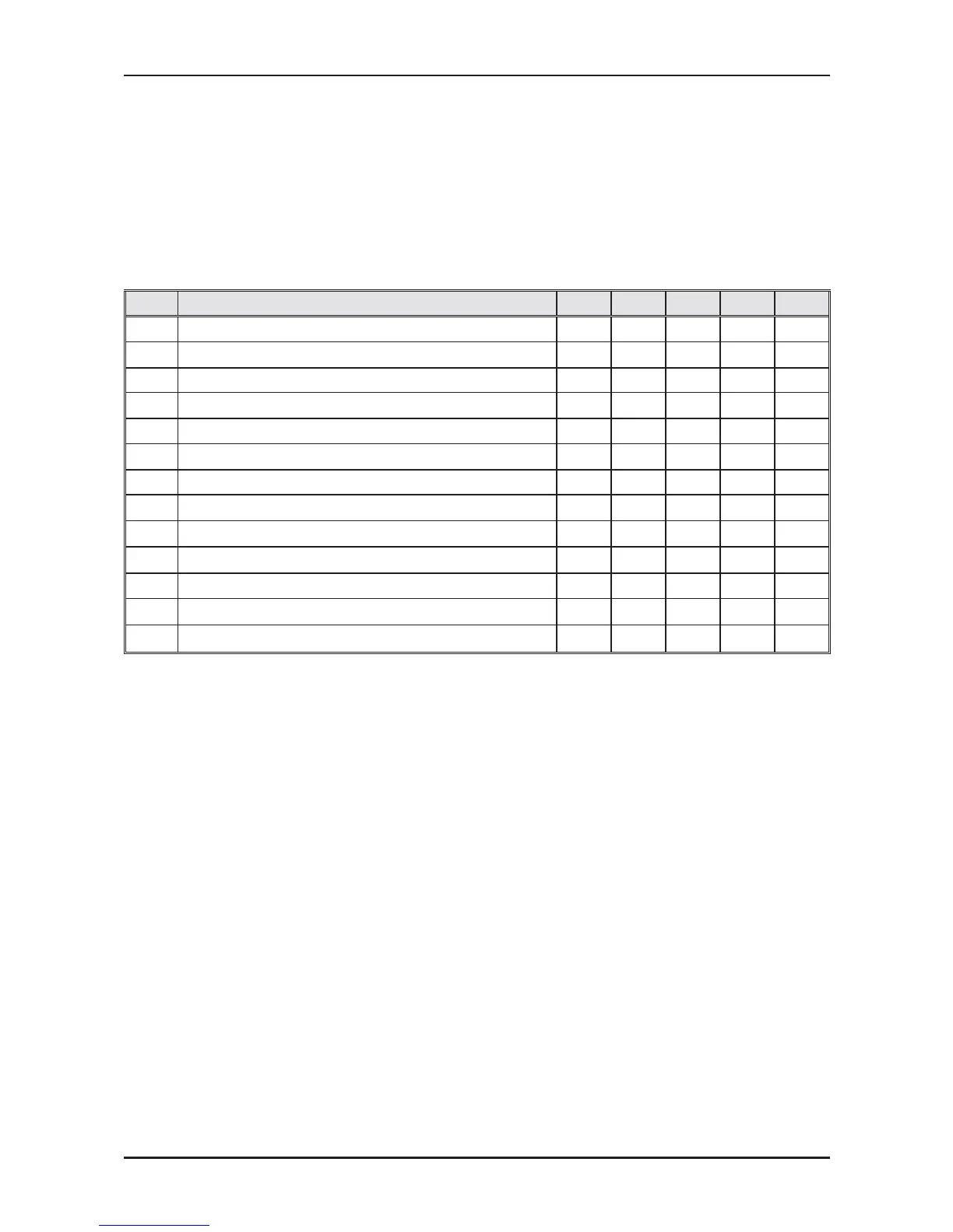
The coding method will be as follow:
Heat led will blink 5 times in 5 seconds, and then will be shut off for the next 5 seconds. Cool led
will blink during the same 5 seconds according to the following table:
No Problem 12345
1 RT1 is disconnected ○●●●●
2 RT1 is shorted ○●●●○
3 RV Fault ○●●○●
4 RT2 is disconnected ●○●●●
5 RT2 is shorted ●○●●○
6 (Reserved) ●○●○●
7 RT2 temp reading doesn’t change ●○●○○
8 RT3 is disconnected ●●○●●
9 RT3 is shorted ●●○●○
10 (Reserved) ●●○○●
11 RT3 temp reading doesn’t change ●●○○○
12 RT2 & RT3 temp reading doesn’t change ●○○○○
13 PG motor no feedback error ●●●●●
○ - ON, ● - OFF
Notes:
1. If faults occur in more than one thermistor (except case number 12 on the table
above), only one fault will be indicated according to the following order: RT3, RT2, RT1.
2. A/C will jump out to normal mode if sending a command by the R/C in the system
diagnostics mode. If this command from the R/C contains a Group ID, this ID will become
the new Group ID of the ELCON unit.
 Loading...