11-1
CONTROL SYSTEM
SM PNXDCI 1-A.1 GB
11. CONTROL SYSTEM
11.1 General Functions and Operating Rules
The DCI software is fully parametric.
All the model dependent parameters are shown in Italic style [ parameter].
The parameters values are given in the last section of this control logic chapter of the service
manual.
11.1.1 System Operation Concept
The control function is divided between indoor and outdoor unit controllers. Indoor unit is the System ‘Master’, requesting
the outdoor unit for cooling/heating capacity supply. The outdoor unit is the system ‘Slave’ and it must supply the required
capacity nless it enters into a protection mode avoiding it from supplying the requested capacity.
The capacity request is transferred via indoor to outdoor communication, and is represented by a parameter called
‘NLOAD’. NLOAD is an integer number with values between 0 and 127, and it represents the heat or cool load felt by the
indoor unit.
11.1.2 Compressor Frequency Control
11.1.2.1 NLOAD setting
The NLOAD setting is done by the indoor unit controller, based on a PI control scheme. The actual NLOAD to be sent to
the outdoor unit controller is based on the preliminary LOAD calculation, the indoor fan speed, and the power shedding
function.
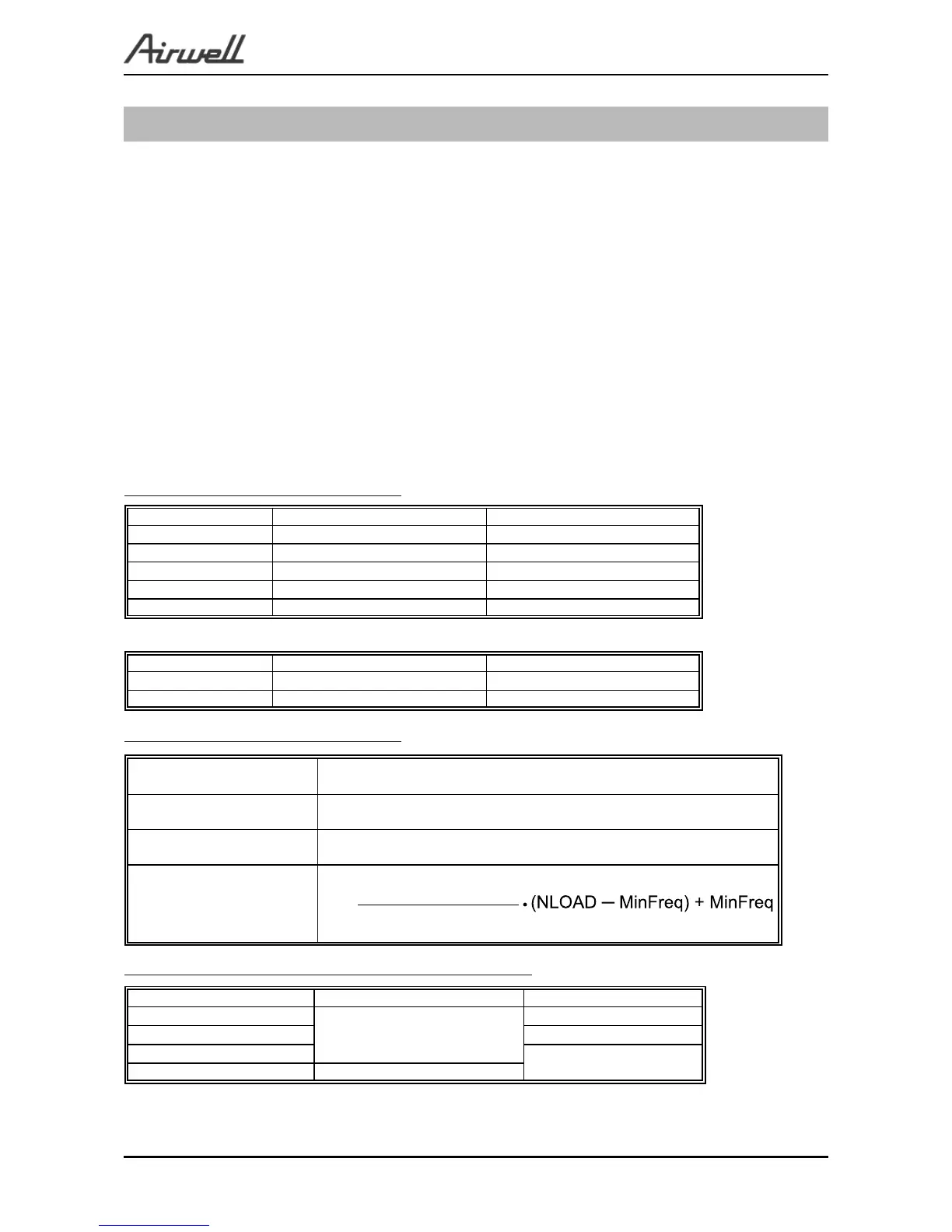
NLOAD limits as a function of indoor fan speed:
Indoor Fan Speed Maximum NLOAD Cooling Maximum NLOAD Heating
Low Max NLOADIF1C 127
Medium Max NLOADIF2C 127
High Max NLOADIF3C 127
Turbo Max NLOADIF4C 127
Auto Max NLOADIF5C 127
NLOAD limits as a function of power shedding:
Mode Power Shedding OFF Power Shedding ON
Cool No limit Nominal Cooling
Heat No limit Nominal Heating
NLOAD limits as a function of indoor fan speed:
NLOAD Target Frequency [Hz]
00
0<NLOAD≤MinFreq MiniFreq
>MinFreq
MaxFreq ─ MinFreq
127 ─ MinFreq
Target frequency limits as a function of outdoor air temperature (OAT):
OAT Range Cool mode limits Heat mode limits
OAT<6
MaxFreqAsOATC
No limit
6<OAT<15 MaxFreqAsOATIH
15 < OAT < 24
MaxFreqAsOAT2H
24 < OAT No limit
 Loading...