5
VI. INSTALLING THE OPTIONAL HEATER ACCESSORY
IMPORTANT NOTE
The optional Heater Accessory is intended to take
the chill out of the indoor air when the air is a few
degrees too cool for comfort. The Heater Accessory
is an effective “chill chaser”. It is not a substitute for
a furnace.
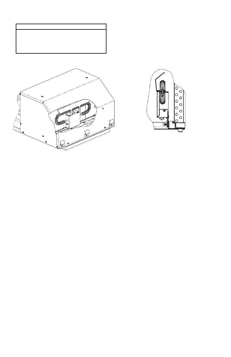
If the heater option is being installed, position the
heater assembly in the Heat Pump return air
opening as shown in Figure 5. The heater bracket
must be installed over the metal basepan
extrusion and positioned between the basepan
and the plastic drain pan (See Figure 6). Tighten
set screw to secure the assembly to prevent
movement. Replace the selector switch control
knob on the ceiling assembly with the knob
provided with the optional heater.
VII. INSTALLING THE CEILING ASSEMBLY (9600 SERIES)
Make sure that you have properly matched the roof
top Heat Pump and interior ceiling assembly. The
following step-by-step instructions must be performed
in the following sequence to insure proper installation.
A. Remove ceiling assembly from carton, separate
individual items and remove the two grilles and
filters from the ceiling shroud.
B. Fasten the duct collar to the heat pump basepan
with 3 provided screws (See Figure 9).
C. Raise the ceiling assembly chute and insert the
supply wiring through the cable clamp and into the
wiring box so that 4-6” of supply conductor is inside
the box. Secure the cable clamp over the supply
wire sheath so that no movement is possible (See
Figure 7).
D. Connect the supply power black conductor to the
black pigtail wire, the white conductor to the white
pigtail wire and the supply ground conductor to the
green pigtail wire found in the wiring box using the
3 provided wire nuts. Using a U.L. approved
electrical tape, secure the wire nuts to wires in a
workmanlike manner (See Figure 8).
E. Press supply conductors and wire nuts into wiring
box and making sure no wires are pinched, secure
the wire box cover with 2 provided screws (See
Figure 8).
F. Plug the heat pump electrical conduit into the 9
position receptacle as shown in Figure 7.
G. If the optional heater accessory package is being
installed, remove the cover from the 2 position
receptacle and plug the heater cord into receptacle
as shown in Figure 7.
H. Raise the ceiling assembly chute to the unit
mounting frame and secure the chute with 4
provided screws (See Figure 9).
I. TIE ALL WIRING TO INSURE NO CONTACT
WITH ANY SHARP EDGES OR WITH OPTIONAL
HEATER IS POSSIBLE. KEEP IN MIND THAT
HIGH VELOCITY AIR WILL BE ENCOUNTERED
IN THIS AREA.
J. Pull the fabric duct material through the ceiling
chute discharge opening. Peel the release liner
from the adhesive strip around the opening. Press
the fabric duct material firmly in place around
opening. Cut off excess fabric on inside of ceiling
chute with a box knife taking care not to tear the
fabric beyond the adhesive strip.
K. Raise the ceiling shroud, ensuring it meshes with
the chute, and secure to mounting frame with 4
provided screws (See Figure 9).
L. Install the control knobs over the switch and
thermostat shafts. The thermostat (temperature)
control knob installs nearest the “Coleman-Mach”
logo.
M. Re-install the filters and grilles into the ceiling
assembly shroud.
N. Turn the selector switch to OFF position.
O. Turn ON the power supply to the roof top heat
pump.
 Loading...