EasyManua.ls Logo

Aiwa AV-D58 Service Manual

Aiwa AV-D58
34 pages
To Next Page IconTo Next Page
Page #1 background imageLoading...
Page #1 background image
SERVICE MANUAL
DATA
STEREO RECEIVER
AV-D58
S/M Code No. 09-016-444-0R2
REVISION
This Service Manual is the "Revision Publishing" and replaces "Simple Manual"
AV-D58 (EZ), (S/M Code No. 09-014-444-0T2).
EZ
All manuals and user guides at all-guides.com
all-guides.com

Other manuals for Aiwa AV-D58

Question and Answer IconNeed help?

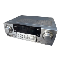
Do you have a question about the Aiwa AV-D58 and is the answer not in the manual?

Aiwa AV-D58 Specifications

General IconGeneral
Power output55 watts per channel into 8Ω (stereo)
Frequency response20Hz to 20kHz
Total harmonic distortion0.5%
Dimensions430 x 140 x 320mm
Weight7.8kg
Tuning rangeFM: 87.5-108 MHz
Input sensitivity150mV (line)
Channel separation50dB
Speaker load impedance8 ohms

Summary

Specifications

Amplifier and Audio Specifications

Power output, distortion, input/output levels, impedance.

General System Specifications

Power requirements, consumption, dimensions, weight.

Main Circuit Board Wiring Diagram

Main Schematic Diagram Part 1

Main C.B (1/2) Circuitry

Details the connections and components of the main circuit board (1/2).

Main Schematic Diagram Part 2

Main C.B (2/2) Circuitry

Details the circuitry of the main circuit board (2/2).

Front Circuit Board Wiring

Front Schematic Diagram

Front C.B Circuit Details

Details the circuitry and components on the front circuit board.

Tuner Circuit Board Wiring

Tuner Schematic Diagram

Tuner C.B Components and Signals

Details components and signal paths on the tuner circuit board.

Peripheral Circuit Board Wiring

Peripheral Circuit Schematics

HP/Video, Volume, Speaker Circuitry

Details circuitry for HP/Video, Volume, and Speaker boards.

Digital Circuit Board Wiring

Digital Schematic Diagram

Digital C.B Circuit Details

Details the circuitry and components on the digital circuit board.

Amplifier Circuit Board Wiring

Amplifier Schematic Diagram

Amplifier C.B Circuitry

Details the circuitry and components on the amplifier circuit board.

Power Supply Circuit Board Wiring

Power Supply Circuit Schematics

IC UPD780228GF-084 Pin Descriptions

Tuner and Front Section Adjustments

Tuner Frequency and Tracking Adjustments

Details procedures for clock frequency, VT, and tracking adjustments for tuners.

AM IF and Output Level Checks

Covers AM IF alignment and output level checks for MW and FM.

Front Section µ-CON OSC Adjustment

Details the adjustment procedure for the µ-CON OSC on the front section.

Related product manuals