EasyManua.ls Logo

Aiwa AX-7400 - Service Manual

Aiwa AX-7400
20 pages
Print Icon
To Next Page IconTo Next Page
Loading...
(SERVICE
MANUAL)
Set
using
ISO
screws
DATE
OF
ISSUE
30/10/1977
SPECIFICATIONS
GENERAL
Semiconductors:
1
IC,
1
FET,
47
transistors,
25
diodes
&
1
LED
AX-7400EE:
120V/220V
(Switchable)
50/60
Hz
AX-7400UK:
AC120V/240V
(Switchable)
50/60
Hz
Power
consumption:
205W
(MAX)
Dimensions:
420(W)
x
150(H)
x
360(D}
mm
Weight:
9.0
kg
Power
source:
FM
TUNER
SECTION
Frequency
ranges:
87
~109
MHz
Intermediate
frequency:
10.7
MHz
+0.1
MHz
Frequency
scale
accuracy:
+150
kHz
(88
MHz}
+200
kHz
(98
MHz)
+150
kHz
(108
MHz)
Noise
limit
sensitivity:
AX-7400EE:
(SN26
dB,
div
40
kHz)
3+2
dB
(88,
98,
108
MHz)
AX-7400UK:
(SN30
dB,
div
75
kHz,
THD
3%)
7
<10dB
(88
MHz)
7<
9B
(98,
108
MHz)
Image
frequency
interference
ratio:
45
>
40
dB
(98
MHz}
Intermediate
frequency
interference
ratio:
75
>
70
dB
(98
MHz)
Muting
sensitivity:
26+4dB
Effective
selectivity:
AX-7400EE:
{tune
out
300
kHz,
div
40
kHz)
60
>
55
dB
AX-7400UK:
(tune
out
400
kHz,
div
75
kHz)
65
>
60
dB
Capture
ratio:
1.5
+1
dB
Separation:
40
>
35
dB
(1
kHz)
SN
ratio:
63
>
58
dB
{input
60
dB)
AM
TUNER
SECTION
Frequency
ranges:
515~1650
kHz
intermediate
frequency:
AX-7400EE:
455
kHz
+5
kHz
AX-7400UK:
468
kHz
+5
kHz
Frequency
scale
accuracy:
+20
kHz
(600
kHz}
+30
kHz
(1000
kHz)
+35
kHz
(1400
kHz)
Noise
limit
sensitivity:
46
<
50
dB
(600,
1000,
1400
kHz)
(SN20
dB)
Image
frequency
interference
ratio:
40
>
35
dB
(1400
kHz)
Intermediate
frequency
interference
ratio:
32
>
25
(input
74
dB,
1000
kHz)
IF
selectivity:
+25/—25
+6
dB
(1000
kHz)
Tuning
hum:
44
>
36
dB
{input
74
dB,
1000
kHz)
AGC
characteristic:
|
50
+5
dB
(1000
kHz)
PRE
AMP
SECTION
<PHONO
AMP
SECTION>
Sensitivity/impedance:
2.5
mV
—52
+2
dB/47
kQ
Gain:
35.5
+1
dB
(1
kHz)
Allowable
input:
120
>
100
mV
(1
kHz
0.5%)
Distortion:
0.4
<
0.5%
(input
100
mV>,
1
kHz)
RIAA
curve
deviation:
+0
+0.8
dB
(30
Hz~15
kHz)
Separation:
35
ah
dB
(1
kHz)
SN
ratio:
65
2
60
dB
<TAPE-1,
AUX
SECTION>
Sensitivity/impedance:
150
mV
—16.5
+2
dB/470
kQ
Gain:
0
+9
dB
(1
kHz)
Distortion:
0.05<
0.1%
Frequency
response:
+0
yp
(99
H2~50
kHz)
Separation:
40
an
dB
SN
ratio:
70
<65
dB
CONTROL
MAIN
AMP
SECTION
Gain:
37.5
+3
dB
(1
kHz)
Tone
controls:
BASS
+8,
—7
dB/+6,
—5
dB
+1.5
dB
(100
Hz)
400/200
Hz
turnover
frequency
TREBLE
+8,
—10
dB/+5,
—6
dB
+1.5
dB
(10
kHz)
2.5/5
kHz
turnover
frequency
Loudness
Response:
+7
+1.5
dB
{100
Hz)
{With
volume
at
-40dB)
+4
+1.5
dB
(10
kHz)
Continuous
power
output:
32W
+
32W
>
30W
+
30W
(420)
1
kHz
{both
channels
driven)
(distortion
0.5%)
Harmonic
Distortion:
0.5%
<
0.8%
(1
kHz,
30W
+
30W)
0.05%
<
0.1%
(1
kHz,
1W
+
1W)
27W
+
27W
>
25W
+
25W
(40
Hz~10
kHz,
distortion
0.5%)
0.6
<
0.8
mV
(482)
Power
bandwidth:
Residual
noise:
®
Specifications
and
external
appearance
are
subject
to
change
without
notice
due
to
product
improvement.
Question and Answer IconNeed help?

Do you have a question about the Aiwa AX-7400 and is the answer not in the manual?

Summary

Specifications

FM Tuner Section

Performance details of the FM tuner section.

AM Tuner Section

Performance details of the AM tuner section.

Preamp Section

Performance details of the pre-amplifier section.

Control Main Amp Section

Performance details of the main amplifier section.

Disassembly Instructions

Top Panel Removal

Steps to remove the top panel for access.

Front Panel Removal

Steps to remove the front panel for access.

Tuner Circuit Board Removal

Steps to remove the tuner circuit board.

Switch Circuit Board Removal

Steps to remove the switch circuit board.

Main Amp;Power Circuit Board Removal

Steps to remove the main amplifier and power circuit boards.

Lamp Circuit Board Removal

Steps to remove the lamp circuit board.

Disassembly Instructions (Continued)

Muting Circuit Board Removal

Steps to remove the muting circuit board.

Control Circuit Board Removal

Steps to remove the control circuit board.

Speaker Switch Circuit Board Removal

Steps to remove the speaker switch circuit board.

Dial Cord Stringing

Dial Cord Stringing Procedure

Guide on how to correctly string the dial cord.

Exploded View-1

Mechanical Parts List

Panel Assembly Parts

List of parts for the main panel assembly.

Front Panel Components

List of parts specific to the front panel.

Cabinet and Related Parts

Parts list for the cabinet and associated components.

Knobs and Buttons

List of control knobs and selector buttons.

Exploded View-2

Electrical Components List

Tuner Circuit Board Components

List of components for the tuner circuit board.

EQ Circuit Board Components

List of components for the EQ circuit board.

Main Amplifier;Power Board Components

List of components for the main amplifier and power board.

Switch Circuit Board Components

List of components for the switch circuit board.

Exploded View-3

Electrical Components List (Continued)

Amp Chassis and Related Parts

List of parts associated with the amplifier chassis.

Antenna and Terminal Parts

Parts for antenna connections and components.

AC Cord and Related Parts

Parts for the AC power cord and connections.

Various Screws and Connectors

List of various types of screws and connectors used.

Accessories and Package Contents

Included Accessories

List of items provided with the unit.

Hardware Nomenclature

Screw and Washer Definitions

Explains different types of screws and washers.

Schematic Diagram

Schematic Diagram (Continued)

Adjustment Procedures

AM-IF Alignment

Steps for aligning the AM Intermediate Frequency.

AM-RF Alignment

Steps for aligning the AM Radio Frequency.

FM-IF Alignment

Steps for aligning the FM Intermediate Frequency.

FM-RF Alignment

Steps for aligning the FM Radio Frequency.

MPX Adjustment

Multiplex (MPX) Adjustment

Procedures for adjusting FM stereo separation.

Adjustment Procedures (Continued)

MPX Adjustment

Procedures for adjusting FM stereo separation.

Level Diagram

Visual representation of signal levels in different sections.

Wiring Diagram-1

Wiring Diagram-1 (Continued)

Wiring Diagram-2

EQ Circuit Board Wiring

Wiring details for the EQ circuit board.

Transistor Circuit Board Wiring

Wiring details for transistor circuit boards.

Main Amplifier;Power Board Wiring

Wiring details for the main amp/power board.

Speaker Selector;Switch Board Wiring

Wiring for speaker selection and switching.

Lamp Circuit Board Wiring

Wiring details for the lamp circuit board.

Wiring Diagram-2 (Continued)

Transistor Circuit Board Wiring

Wiring details for transistor circuit boards.

Muting Circuit Board Wiring

Wiring details for the muting circuit board.

Main Amplifier;Power Board Wiring

Wiring details for the main amp/power board.

Lamp Circuit Board Wiring

Wiring details for the lamp circuit board.

Electrical Main Parts List

Tuner Circuit Board Parts

Component list for the tuner circuit board.

EQ Circuit Board Parts

Component list for the EQ circuit board.

Main Amp;Power Board Parts

Component list for the main amp/power board.

Control Circuit Board Parts

Component list for the control circuit board.

Switch Circuit Board Parts

Component list for the switch circuit board.

Electrical Main Parts List (Continued)

Speaker Switch Board Parts

Component list for the speaker switch board.

Transistor Circuit Board Parts

Component list for the transistor circuit boards.

Fuse Circuit Board Parts

Component list for the fuse circuit board.

Miscellaneous Parts

List of various miscellaneous components.

Muting Circuit Board Parts

Component list for the muting circuit board.

Speaker Terminal Board Parts

Component list for the speaker terminal board.

Antenna Circuit Board Parts

Component list for the antenna circuit board.

Lamp Circuit Board Parts

Component list for the lamp circuit board.

Meter Circuit Board Parts

Component list for the meter circuit board.

Overview

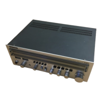
The AIWA AX-7400EE (UK model) is an FM/AM Stereo Receiver, designed to provide high-fidelity audio reproduction and versatile connectivity. This service manual outlines its technical specifications, disassembly procedures, adjustment steps, and parts lists, offering a comprehensive overview for maintenance and repair.

Function Description

The AX-7400EE serves as the central hub for an audio system, integrating an FM/AM tuner, a pre-amplifier, and a main amplifier into a single unit. It allows users to:

  • Receive FM and AM broadcasts: The integrated tuner section provides access to radio stations across the FM (87-109 MHz) and AM (515-1650 kHz) bands.
  • Connect and amplify various audio sources: The pre-amplifier section supports multiple inputs, including:
    • Phono: For connecting a turntable, with RIAA equalization and appropriate sensitivity for magnetic cartridges.
    • Tape-1 and Tape-2/AUX: For connecting tape decks, CD players, or other line-level audio sources.
  • Control audio characteristics: Tone controls (Bass and Treble) and a Loudness response feature allow users to tailor the sound to their preferences and listening environment.
  • Drive loudspeakers: The main amplifier section provides sufficient power output to drive a pair of stereo loudspeakers.
  • Monitor audio signals: Tape monitor functions allow for real-time monitoring of recording signals.
  • Connect headphones: A dedicated headphone jack is provided for private listening.

Important Technical Specifications

The AX-7400EE boasts a robust set of specifications, indicating its performance capabilities:

  • General:

    • Semiconductors: 1 IC, 1 FET, 47 transistors, 25 diodes, and 1 LED.
    • Power Source: Switchable 120V/220V (50/60 Hz) for the EE model and 120V/240V (50/60 Hz) for the UK model.
    • Power Consumption: 205W (MAX).
    • Dimensions: 420(W) x 150(H) x 360(D) mm.
    • Weight: 9.0 kg.
  • FM Tuner Section:

    • Frequency Ranges: 87-109 MHz.
    • Intermediate Frequency: 10.7 MHz ±0.1 MHz.
    • Noise Limit Sensitivity:
      • AX-7400EE: 3±2 dB (SN26 dB, div 40 kHz) at 88, 98, 108 MHz.
      • AX-7400UK: 7≤10 dB (SN30 dB, div 75 kHz, THD 3%) at 88 MHz, and 7≤9 dB at 98, 108 MHz.
    • Image Frequency Interference Ratio: 45≥40 dB (98 MHz).
    • Intermediate Frequency Interference Ratio: 75≥70 dB (98 MHz).
    • Effective Selectivity:
      • AX-7400EE: 60≥55 dB (tune out 300 kHz, div 40 kHz).
      • AX-7400UK: 65≥60 dB (tune out 400 kHz, div 75 kHz).
    • Capture Ratio: 1.5±1 dB.
    • Separation: 40≥35 dB (1 kHz).
    • SN Ratio: 63≥58 dB (input 60 dB).
  • AM Tuner Section:

    • Frequency Ranges: 515-1650 kHz.
    • Intermediate Frequency:
      • AX-7400EE: 455 kHz ±5 kHz.
      • AX-7400UK: 468 kHz ±5 kHz.
    • Noise Limit Sensitivity (SN20 dB): 46≤50 dB (600, 1000, 1400 kHz).
    • Image Frequency Interference Ratio: 40≥35 dB (1400 kHz).
    • Intermediate Frequency Interference Ratio: 32≥25 dB (input 74 dB, 1000 kHz).
    • IF Selectivity: ±25/+6 dB (1000 kHz).
    • AGC Characteristic: 44≥36 dB (input 74 dB, 1000 kHz).
    • Tuning Hum: 50±5 dB (1000 kHz).
  • Pre Amp Section:

    • Phono Amp Section:
      • Sensitivity/Impedance: 2.5 mV -52 +2 dB/47 kΩ.
      • Gain: 35.5±1 dB (1 kHz).
      • Allowable Input: 120≥100 mV (1 kHz 0.5%).
      • Distortion: 0.4≤0.5% (input 100 mV≥, 1 kHz).
      • RIAA Curve Deviation: ±0.8 dB (30 Hz-15 kHz).
      • Separation: 35≥30 dB (1 kHz).
      • SN Ratio: 65≥60 dB.
    • Tape-1, AUX Section:
      • Sensitivity/Impedance: 150 mV -16.5 +2 dB/470 kΩ.
      • Gain: 0±0 dB (1 kHz).
      • Distortion: 0.05≤0.1%.
      • Frequency Response: +0/-1 dB (20 Hz-50 kHz).
      • Separation: 40≥35 dB.
      • SN Ratio: 70≥65 dB.
  • Control Main Amp Section:

    • Gain: 37.5±3 dB (1 kHz).
    • Tone Controls:
      • Bass: +8/-7 dB/+6/-5 dB ±1.5 dB (100 Hz), with 400/200 Hz turnover frequency.
      • Treble: +8/-10 dB/+5/-6 dB ±1.5 dB (10 kHz), with 2.5/5 kHz turnover frequency.
    • Loudness Response (volume at -40dB): +7±1.5 dB (100 Hz), +4±1.5 dB (10 kHz).
    • Continuous Power Output (1 kHz, both channels driven, distortion 0.5%): 32W + 32W ≥ 30W + 30W (4Ω).
    • Harmonic Distortion: 0.5%≤0.8% (1 kHz, 30W + 30W), 0.05%≤0.1% (1 kHz, 1W + 1W).
    • Power Bandwidth (40 Hz-10 kHz, distortion 0.5%): 27W + 27W ≥ 25W + 25W.
    • Residual Noise: 0.6≤0.8 mV (4Ω).

Usage Features

The AX-7400EE is designed for user-friendly operation with several key features:

  • Selector Switch: Allows easy switching between various input sources (Phono, FM, AM, Tape-1, Tape-2/AUX).
  • Tone Controls: Independent Bass and Treble controls for sound customization.
  • Loudness Function: Boosts bass and treble frequencies at low listening levels to compensate for human hearing characteristics.
  • Stereo/Mono Switch: For optimizing FM reception, allowing users to switch between stereo and mono modes.
  • FM Muting: Reduces inter-station noise during FM tuning.
  • AFC (Automatic Frequency Control): Helps stabilize FM tuning.
  • Speaker Selector: Allows selection of different speaker pairs (A, B, or A+B).
  • Headphone Jack: Convenient front-panel access for private listening.
  • Dial Scale: Clearly marked frequency dial for precise tuning.
  • Tuning Meter: Provides visual indication of signal strength and accurate tuning.

Maintenance Features

The service manual provides detailed instructions for maintenance and repair, making the AX-7400EE serviceable:

  • Disassembly Instructions: Step-by-step guides for removing the top panel, front panel, tuner circuit board, switch circuit board, main amp/power circuit board, and lamp circuit board. This facilitates access to internal components for inspection and repair.
  • Dial Cord Stringing Diagram: A clear diagram for correctly re-stringing the dial cord, a common maintenance task for older tuners.
  • Exploded Views: Detailed diagrams showing the arrangement of all mechanical parts, aiding in reassembly and identification of components.
  • Parts Lists: Comprehensive lists of mechanical and electrical parts, including part numbers, descriptions, and quantities, essential for ordering replacements.
  • Schematic Diagrams: Electrical schematics for all circuit boards (Tuner, EQ, Main Amp/Power, Control, Switch, Muting, Transistor, Speaker Terminal, ANT, Lamp, Meter), allowing technicians to trace signal paths and troubleshoot electrical issues.
  • Wiring Diagrams: Illustrate the interconnections between different circuit boards and external components.
  • Adjustments: Detailed procedures for AM-IF, AM-RF, FM-IF, FM-RF, Regulator, and MPX adjustments, ensuring optimal performance after repairs or component replacements. These include specific signal sources, connection points, and adjustment steps.
  • Level Diagram: Provides a visual representation of signal levels at various stages of the audio path, useful for diagnosing signal loss or distortion.
  • Hardware Nomenclature: Explains the naming convention for screws and other hardware, simplifying parts identification.

The AIWA AX-7400EE is a well-engineered stereo receiver, offering a blend of performance, features, and maintainability, making it a valuable component for any vintage audio enthusiast.

Aiwa AX-7400 Specifications

General IconGeneral
BrandAiwa
ModelAX-7400
CategoryStereo Receiver
LanguageEnglish

Related product manuals