SERVICE MANUAL
Sony Corporation
Home Audio Company
Published by Sony Engineering Corporation
US Model
Canadian Model
AEP Model
UK Model
E Model
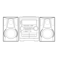
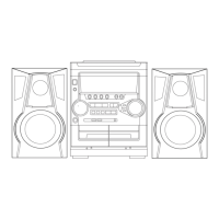
MICRO HI-FI COMPONENT SYSTEM
9-877-858-01
2004E16-1
© 2004.05
Ver 1.0 2004.05
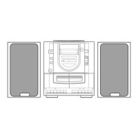
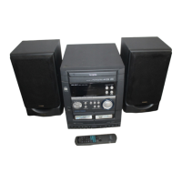
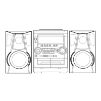
AWP-ZX7
PARTS LIST
Part No. Description Remark
ACCESSORIES
************
1-478-520-11 COMMANDER, STANDARD (RM-Z20051)
(INCLUDING BATTERY COVER)
1-754-102-31 ANTENNA, LOOP (LW.MW)
1-754-243-11 ANTENNA (FM)
0 1-770-019-51 ADAPTOR, CONVERSION PLUG (UK)
1-793-184-23 CONNECTOR (F TYPE ADAPTOR)
1-823-704-11 CUSHION CORD, CONNECTION (USB)
4-210-254-02 CUSHION (FOOT)(FOR SPEAKER)
4-254-179-11 MANUAL, INSTRUCTION (ENGLISH)(EXCEPT KR)
4-254-179-21 MANUAL, INSTRUCTION (FRENCH)(CND, AEP, SP)
4-254-179-31 MANUAL, INSTRUCTION (SPANISH)(US, AEP, SP, E51)
4-254-179-41 MANUAL, INSTRUCTION (CZECH, GERMAN, HANGARIAN,
ITALIAN, POLISH, RUSSIAN)(AEP)
4-254-179-51 MANUAL, INSTRUCTION (CHINESE)(SP)
4-254-179-61 MANUAL, INSTRUCTION (KOREAN)(KR)
•AWP-ZX7 is composed of following models.
As for the service manual, it is issued for each
component model, then, please refer to them.
COMPONENT MODEL NAME
COMPACT DISK DECK
RECEIVER SYSTEM
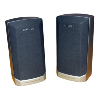
SPEAKER SYSTEM
AWP-ZX7
CX-LZX7
SSX-LZX7
•Abbreviation
CND : Canadian model
E51 : Chilean and Peruvian models
KR : Korean model
SP : Singapore model
The components identified by
mark 0 or dotted line with mark
0 are critical for safety.
Replace only with part number
specified.
Les composants identifiés par
une marque 0 sont critiques
pour la sécurité.
Ne les remplacer que par une
pièce portant le numéro spécifié.