Do you have a question about the Aiwa XH-A1000 and is the answer not in the manual?
Details on tuner, amplifier, inputs, and outputs for the main unit.
Technical details of the cassette deck, including format and heads.
Specifications for the CD player, including laser, converter, and performance.
General specifications including power, dimensions, and weight of the main unit.
Specifications for the SX-WA1000 speaker system, including cabinet and drivers.
Specifications for the SX-R1800 speaker system, covering drivers and dimensions.
Specifications for the SX-C1800 speaker system, including drivers and dimensions.
Important warnings regarding eye safety when servicing laser components.
Cautions for avoiding hazardous radiation exposure during servicing.
French caution regarding hazardous radiation exposure during servicing.
Norwegian/Danish caution for hazardous radiation exposure during servicing.
Finnish caution regarding hazardous radiation exposure during servicing.
Swedish caution regarding hazardous radiation exposure during servicing.
Precautions for replacing the optical block, including static discharge.
Procedure for safely discharging power supply capacitors before repair.
Checks to perform before replacing the microcomputer to confirm defect.
Checking the HOLD terminal voltage for microcomputer diagnosis.
Procedure for performing a forced reset on the microcomputer.
Checking the soldering state of the microcomputer before replacement.
Step to remove outer casing screws and the steel casing.
Step to remove three screws from the bottom of the unit.
Step to remove four screws from both sides of the unit.
Step to remove rear casing assembly screws.
Step to disconnect flexible flat cables from the PWB.
Step to remove the rear CD panel.
Step to remove the 3CD chassis with the CD mechanism.
Step to remove the CD mechanism from the chassis.
Information on servicing the CD mechanism using a jig.
List of integrated circuits used in the main unit.
List of transistors used in the main unit.
List of diodes used in the main unit.
List of components on the main circuit board (Capacitors).
List of capacitors C238 through C810 with part numbers and types.
List of capacitors C811 through C863 with part numbers and types.
List of capacitors C864 through C933 with part numbers and types.
List of connectors and flexible flat cables.
List of components on the Front Circuit Board.
List of capacitors C253 through C962 with part numbers and types.
List of additional connectors and flexible flat cables.
List of LED components used in the unit.
List of switches used in the unit.
List of remaining switches.
List of components on the Key Circuit Board.
List of components on the Low Amp Circuit Board.
List of components on the 5 Channel Amp Circuit Board.
List of components on the Video I/O Circuit Board.
List of components on the Video Jack Circuit Board.
List of components on the Video-3 Circuit Board.
List of components on the Connect Circuit Board.
List of components on the Tuner Circuit Board.
List of components on the PT Circuit Board.
List of components on the SCART Circuit Board.
List of components on the Microphone Circuit Board.
List of components for LED A, B, C, and D Circuit Boards.
List of components on the Deck Circuit Board.
List of components on the Deck Motor Circuit Board.
List of components on the Fan Circuit Board.
Explanation of the structure and meaning of chip resistor part codes.
Details on chip resistors, including wattage, tolerance, and dimensions.
Illustrations and part numbers for various transistors.
Illustrations and part numbers for additional transistors.
Illustrations and part numbers for FET transistors.
Illustrations and part numbers for more FET transistors.
Wiring diagram for the main circuit board.
Wiring diagram for the fan circuit board.
Schematic of the main circuit board's amplifier section.
Connections from the front circuit board to the main board.
Connection from the tuner circuit board to the main board.
Connection from the video I/O circuit board to the main board.
Schematic of the main circuit board's power supply section.
Connections to/from the amplifier section of the main board.
Schematic of the main circuit board's deck section.
Connection to the head circuit board.
Connections to/from the amplifier section for the deck.
Schematic of the main circuit board's Pro Logic section.
Connections to/from the amplifier section for Pro Logic.
Connections to/from the power supply section for Pro Logic.
Solder points connecting the fan to the main circuit board.
Schematic of the fan circuit board.
Connector details for the fan.
Wiring diagram for the front circuit board.
Wiring diagram for the connect circuit board.
Schematic of the front circuit board.
Schematic of the deck circuit board.
Schematic of the deck motor circuit board.
Connections from front/deck boards to the main amp section.
Wiring diagram for the operate circuit board.
Wiring diagram for the key circuit board.
Wiring diagram for the microphone circuit board.
Wiring diagrams for LED circuit boards.
Wiring diagram for the LED-A circuit board.
Schematic of the key circuit board.
Schematic of the operate circuit board.
Schematics for LED circuit boards.
Schematic of the microphone circuit board.
Connections from main board to low amp board.
Connection from low amp board to PT board.
Wiring diagram for the low amp circuit board.
Schematic of the low amp circuit board.
Connections from main amp section to low amp board.
Connection from low amp board to PT board.
Connections from main board to 5 channel amp board.
Wiring diagram for the 5 channel amp circuit board.
Schematic of the 5 channel amp circuit board.
Connections from main amp section to 5 channel amp board.
Wiring diagram for the video I/O circuit board.
Wiring diagram for the video jack circuit board.
Wiring diagram for the video-3 circuit board.
Wiring diagram for the SCART circuit board.
Wiring connections between video, SCART, and connect boards.
Schematic of the video jack circuit board.
Schematic of the video I/O circuit board.
Schematic of the video-3 circuit board.
Schematic of the connect circuit board.
Connections to main and SCART boards.
Schematic of the SCART circuit board.
Connection from Video I/O board to SCART board.
Details of SCART connectors.
Wiring diagram for the tuner circuit board.
Connections from tuner board to the main circuit board.
Schematic of the tuner circuit board.
Connections from tuner to main board sections.
Connections from low amp board to PT board.
Connections from main board to PT board.
Wiring diagram for the PT circuit board.
Schematic of the PT circuit board.
Connection from low amp board to PT board.
Connection from main board to PT board.
Wiring diagram for the deck circuit board.
Wiring diagram for the head circuit board.
Wiring diagram for the deck motor circuit board.
Connections from front board to deck and motor boards.
Connection from deck board to main circuit board.
Diagram showing the grid assignment for the FL display.
Table detailing anode connections for the FL display.
Diagram showing the segment designation for the FL display.
Grid assignment diagram for the BJ734GK FL display.
Anode connection table for the BJ734GK FL display.
Segment designation diagram for the BJ734GK FL display.
Block diagram for the CXA1553P integrated circuit.
Block diagram for the M62445AFP integrated circuit.
Block diagram for the HD74HC4051FP integrated circuit.
Block diagram for the BU4094BCF integrated circuit.
Block diagram for the BU1920FS integrated circuit.
Block diagram for the LC72131D integrated circuit.
Block diagram for the BA7625 integrated circuit.
Block diagram for the M62463AFP integrated circuit.
Block diagram for the LA1837NL integrated circuit.
Block diagram for the M62491FP integrated circuit.
Block diagram for the BA3835F integrated circuit.
Block diagram for the BA3880FS integrated circuit.
Detailed description of the LC87F65C8A IC pins and functions.
Further details on LC87F65C8A IC pins and functions.
Detailed description of the LC72131D IC pins and functions.
Procedure to adjust tape speed using a test tape.
Procedure to adjust head azimuth for optimal output.
Adjusting playback response and sensitivity for deck.
Procedure to adjust the microcomputer clock frequency.
Checking the tuner's clock frequency.
Alignment and checks for MW, LW, and FM tuning stages.
Adjusting DC balance and mono distortion.
Checking output signal levels for MW and FM.
Table defining color symbols used in the mechanical parts list.
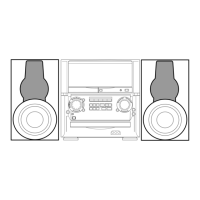
Instructions for disassembling Type 1 speakers.
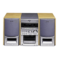
Instructions for disassembling Type 2 speakers.
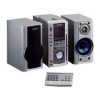
Instructions for disassembling Type 3 speakers.
List of tools required for speaker disassembly.
Step-by-step guide to remove the front panel.
Step-by-step guide to attach the front panel.
| Type | Mini Hi-Fi System |
|---|---|
| Speaker Type | 2-Way Bass Reflex |
| Frequency Response | 40Hz - 20kHz |
| Total Harmonic Distortion | 0.5% |
| Speaker Impedance | 6 Ohms |
| Video Connections | No |
| Speakers | 2 |
| CD Player | Yes |
| Radio Tuner | FM |
| Bluetooth | Yes (Version 4.2) |