EasyManua.ls Logo

Aiwa xr-md500 User Manual

Aiwa xr-md500
70 pages
To Next Page IconTo Next Page
Page #1 background imageLoading...
Page #1 background image
BASIC MD MECHANISM : ZZG-2 A
BASIC CD MECHANISM : ZZG-4 A
BASIC TAPE MECHANISM : 2ZM-1 YR9N
MD/CD STEREO SYSTEM
XR-MD500
S/M Code No. 09-995-328-5R1
D(S)
SERVICE MANUAL
REVISION
DATA
MODEL CODE : 8ZCL4-0130(S)
このサービスマニュアルはシンプル版(S/MCodeNo.09-995-328-5T1)の改定版です。
差し替えて使用してください。
w
w
w
.
x
i
a
o
y
u
1
6
3
.
c
o
m
Q
Q
3
7
6
3
1
5
1
5
0
9
9
2
8
9
4
2
9
8
T
E
L
1
3
9
4
2
2
9
6
5
1
3
9
9
2
8
9
4
2
9
8
0
5
1
5
1
3
6
7
3
Q
Q
TEL 13942296513 QQ 376315150 892498299
http://www.xiaoyu163.com
Question and Answer IconNeed help?

Do you have a question about the Aiwa xr-md500 and is the answer not in the manual?

Aiwa xr-md500 Specifications

General IconGeneral
TypeMini Stereo System
FunctionsCD Player, MD Player/Recorder, Radio Tuner, Amplifier
CD PlayerYes
MD Player/RecorderYes
Radio TunerAM/FM
Speakers2-way speakers

Summary

SPECIFICATIONS

Repair Safety Precautions

Electrical Main Parts List

Block Diagrams

Block Diagram-1 (Main)

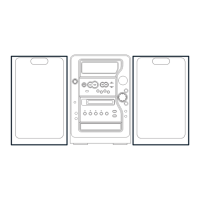
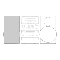
System block diagram for the main unit.

Block Diagram-2 (CD)

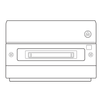
Block diagram of the CD mechanism and related circuits.

Block Diagram-3 (MD)

Block diagram of the MD mechanism and related circuits.

Block Diagram-4 (Tuner)

Block diagram of the Tuner section.

Test Mode Operations

CD Section Test Mode

Procedures for entering and operating the CD section test mode.

CD Section Test Mode Operations

MD Section Test Mode Operations

Laser Power Confirmation

Electrical Adjustment - Tuner Section

IC Descriptions

Mechanical Exploded Views and Parts Lists

Mechanical Exploded View 1/1

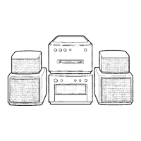
Exploded diagram of the overall mechanical assembly.

Mechanical Parts List 1/1

List of all mechanical parts with part numbers and descriptions.

Tape Mechanism Exploded View 1/1

Tape Mechanism Parts List 1/1

Related product manuals