EasyManua.ls Logo

Aiwa XR-MD510 User Manual

Aiwa XR-MD510
26 pages
To Next Page IconTo Next Page
Page #1 background imageLoading...
Page #1 background image
SERVICE MANUAL
DATA
MD / CD
STEREO SYSTEM
BASIC TAPE MECHANISM : 2ZM-1 YR9NF
BASIC CD MECHANISM : 3ZG-3 YE3NC
BASIC MD MECHANISM : AZG-4A
XR-MD510
XR-MD511
D,K
EZ
S/M Code No. 09-004-422-8S1
SUPPLEMENT
This Service Manual contains the additional information “DISASSEMBLY INSTRUCTION”
and “TEST MODE” for the model XR-MD510/511(K/EZ).
If requiring the other information, see Service Manual of XR-MD510(D,K) / 511(EZ),
(S/M Code No. 09-004-422-8R1).
MODEL CODE : 8ACJ4-0130 (S)
8ACJ4-0133 (SM)
XR–MD510/511
SYSTEM
SPEAKER
SX-M510
w
w
w
.
x
i
a
o
y
u
1
6
3
.
c
o
m
Q
Q
3
7
6
3
1
5
1
5
0
9
9
2
8
9
4
2
9
8
T
E
L
1
3
9
4
2
2
9
6
5
1
3
9
9
2
8
9
4
2
9
8
0
5
1
5
1
3
6
7
3
Q
Q
TEL 13942296513 QQ 376315150 892498299
http://www.xiaoyu163.com
Question and Answer IconNeed help?

Do you have a question about the Aiwa XR-MD510 and is the answer not in the manual?

Aiwa XR-MD510 Specifications

General IconGeneral
TypeMini Hi-Fi System
Disc Capacity1
Media TypeCD, MD
TunerFM/AM
MD Player/RecorderYes
Remote ControlYes
FunctionsRadio

Summary

Disassembly Instructions

Removing Outer Appearance Parts

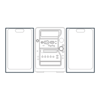
Instructions for removing external panels and covers from the unit's casing.

Removing the PWB, CD ACJ-4

Steps to detach the Printed Wiring Board (PWB) for the CD mechanism.

Removing the FRONT Block

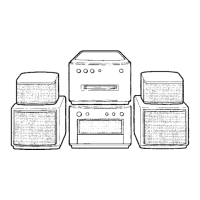
Procedure for removing the front section of the device, including associated boards.

Removing the MD Block (AZG-4)

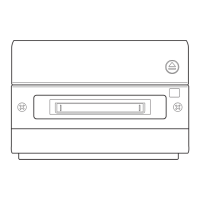
Detailed steps for disassembling and removing the MD mechanism module.

Service Jig and Tools

Service Jig and Tools Overview

Information on specialized jigs and tools, including extension FFCs for repair.

Re-assembly Notes

Gear Phase Adjustment

Procedure for aligning the phase of gears during reassembly.

HLDR, GEAR ASSY Installation Procedure

Steps for correctly installing the Holder, Gear Assembly.

CD Test Mode Operations

Starting Up and Releasing CD Test Mode

Instructions for activating, deactivating, and exiting the CD Test Mode.

CD Test Mode Function Description

Explanation of the functions and indications available within CD Test Mode.

MD Test Mode Operations

MD Test Mode Startup and Control

Steps to start, confirm, and operate the MD Test Mode.

MD Test Mode Release and Servo Standby

Procedures to exit MD Test Mode and switch to servo standby.

Servo Operation Checks

Methods to verify the functionality of servo systems in MD Test Mode.

Electrical Adjustment Procedures

Temperature Compensation Adjustment

Procedure for adjusting temperature compensation for the MD block.

Laser Power Adjustment

Steps for adjusting playback and recording laser power levels.

Automatic Sequence Adjustments (MO/PIT Disks)

Performing automatic adjustments for MO and PIT disk operations.

EEP-ROM Initialization

Procedure to reset EEP-ROM to default values.
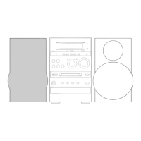
Related product manuals