Do you have a question about the Aiwa XR-MP50 and is the answer not in the manual?
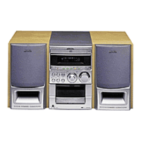
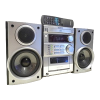
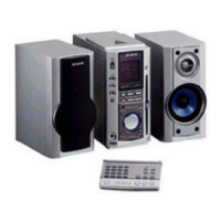
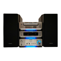
Technical details of the main audio system unit.
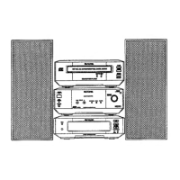
Technical details of the speaker system units.
Guidelines to protect eyes from laser radiation during servicing.
Precautions for replacing the optical pickup block.
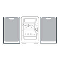
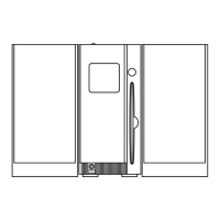
Steps to remove external panels like side and top covers.
Procedures for removing CD, Main, and other internal boards.
Steps to remove the CD mechanism board (3ZG-3).
Guidance on aligning gears during re-assembly.
Steps for installing the gear assembly holder.
List of electrical components including ICs, transistors, and diodes.
List of mechanical components for the main unit.
List of parts for the tape deck mechanism.
List of parts for the CD player mechanism (3ZG-3).
Wiring diagram for the main circuit board.
Wiring diagrams for front panel and switch boards.
Wiring and schematic diagrams for the CD section.
Wiring and schematic diagrams for the tuner.
Wiring diagram for the deck and head mechanism.
Block diagrams illustrating the internal structure of key ICs.
Detailed pinout and function descriptions for various ICs.
Procedures for adjusting tuner frequency, tracking, and VT.
Procedures for adjusting tape speed, azimuth, and frequency response.
Procedure for the µ-CON OSC adjustment.
Steps to enter and exit the CD test mode.
Description of available functions within CD test mode.
Instructions for disassembling speaker units and panels.
List of speaker parts and included accessories.
| Type | Mini Hi-Fi System |
|---|---|
| CD Player | Yes |
| Radio Tuner | AM/FM |
| Playable Media | CD, Cassette |
| Remote Control | Yes |