EasyManua.ls Logo

Aiwa XS-G3 SERIES User Manual

Aiwa XS-G3 SERIES
49 pages
To Next Page IconTo Next Page
Page #1 background imageLoading...
Page #1 background image
SERVICE MANUAL
DATA
COMPACT DISC
STEREO SYSTEM
BASIC TAPE MECHANISM : BZM-1 R1NM
BASIC CD MECHANISM : BZG-5 ZD3NM
XS-G3
XS-G4
XS-G5
U,LH,EZ,K
EZ
EZ,K
S/M Code No. 09-013-441-5R1
REVISION
SPEAKERSYSTEM
CD
CASSEIVER
REMOTE
CONTROLLER
XS–G3(U,LH) RC–BAS11CX–G3 SX–G3
RC–BAS03XS–G3(EZ,K) CX–G3 SX–G3
RC–BAS11XS–G4(EZ) CX–G4 SX–G4
RC–BAS11XS–G5(EZ) CX–G5 SX–G5
RC–BAS03XS–G5(K) CX–G5 SX–G5
This Service Manual is the "Revision Publishing" and replaces "Simple Manual"
XS-G3 (U,LH,EZ,K) / XS-G4 (EZ) / XS-G5 (EZ,K), (S/M Code No. 09-012-441-5T1).
If requiring information about the CD mechanisim, see Service Manual of BZG-5,
(S/M Code No. 09-00C-353-3N2)
Question and Answer IconNeed help?

Do you have a question about the Aiwa XS-G3 SERIES and is the answer not in the manual?

Aiwa XS-G3 SERIES Specifications

General IconGeneral
BrandAiwa
ModelXS-G3 SERIES
CategoryStereo System
LanguageEnglish

Summary

Specifications

FM Tuner Section Specifications

Details of the FM tuner section, including tuning range and sensitivity.

AM/MW Tuner Section Specifications

Specifications for the AM/MW tuner section, covering tuning range and sensitivity.

LW Tuner Section Specifications

Specifications for the LW tuner section, including tuning range and sensitivity.

Amplifier Section Specifications

Details on power output and total harmonic distortion.

Cassette Deck Section Specifications

Specifications for the cassette deck, including track format and frequency response.

Compact Disc Player Section Specifications

Specifications for the CD player, covering laser, D/A converter, and S/N ratio.

Speaker System Specifications

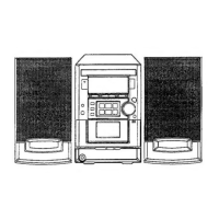
Specifications for speaker systems SX-G3, SX-G4, and SX-G5.

Laser Safety and Precautions

Laser Beam Exposure Warnings

Warnings and cautions regarding laser beam exposure during servicing.

Optical Block Replacement Precautions

Steps for safely replacing the optical block, including static discharge precautions.

Pre-Repair Procedures

Disassembly Instructions

Phase Alignment Procedures

Main Electrical Parts List

Wiring Diagram - Main/Jack (EZ, K)

Schematic Diagram - Amplifier/Head (EZ, K)

Schematic Diagram - Tuner Section (EZ, K)

Wiring Diagram - Main/Jack/Fan (U, LH)

Schematic Diagram - Amplifier/Head (U, LH)

Schematic Diagram - Tuner Section (U, LH)

Schematic Diagram - Jack Section (U, EZ, K)

Wiring Diagram - Front (Part 1)

Wiring Diagram - Front (Part 2)

Wiring Diagram - Top/Motor/Mic/Key

Wiring Diagram - Power Transformer (U, EZ, K)

Schematic Diagram - Power Transformer (U)

Schematic Diagram - Power Transformer (EZ, K)

Wiring Diagram - Power Transformer (LH)

Schematic Diagram - Power Transformer (LH)

Wiring Diagram - Deck/Head

Adjustment Procedures

Tuner Section Adjustments

Calibration steps for the tuner section (Clock, AM/MW VT, Tracking, FM VT, FM Tracking).

Deck Section Adjustments

Calibration steps for the tape deck section (Tape Speed, Head Azimuth, Frequency Response).

Front Section Adjustment

Procedure for adjusting the oscillator in the front section.

CD Test Mode Operations

Mechanical Parts List (U, LH, K)

Mechanical Parts List (EZ)

Tape Mechanism Parts List

Speaker Disassembly Instructions

Related product manuals