EasyManua.ls Logo

Aiwa XS–G6 User Manual

Aiwa XS–G6
23 pages
To Next Page IconTo Next Page
Page #1 background imageLoading...
Page #1 background image
SERVICE MANUAL
DATA
COMPACT DISC
STEREO SYSTEM
BASIC TAPE MECHANISM : BZM-1 R1NM
BASIC CD MECHANISM : BZG-5 ZD3NM
XS-G6
EZ
S/M Code No. 09-015-441-5S1
SUPPLEMENT
SPEAKERSYSTEM
CD
CASSEIVER
REMOTE
CONTROLLER
XS–G6 RC–BAS11CX–G6
SX–G6
SX–S5
• This Service Manual contains information about the difference between
XS-G6 (EZ) and XS-G4 (EZ). If requiring other information, see Service Manual of
XS-G3 (U,LH,EZ,K) / XS-G4 (EZ) / XS-G5 (EZ,K), (S/M Code No. 09-013-441-5R1).
If requiring information about the CD mechanisim, see Service Manual of BZG-5,
(S/M Code No. 09-00C-353-3N2)
Question and Answer IconNeed help?

Do you have a question about the Aiwa XS–G6 and is the answer not in the manual?

Aiwa XS–G6 Specifications

General IconGeneral
BrandAiwa
ModelXS–G6
CategoryStereo System
LanguageEnglish

Summary

Specifications

FM, MW, LW Tuner Specifications

Details specifications for FM, MW, and LW tuner sections.

Amplifier and Speaker System Specifications

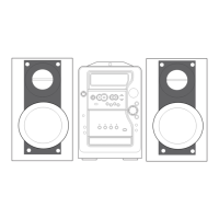
Lists specifications for amplifier, subwoofer, and satellite speakers.

Cassette Deck and CD Player Specifications

Covers specifications for cassette deck and CD player sections.

General System Specifications

Includes general power, dimensions, weight, and system details.

Electrical Main Parts List

Component Illustrations

Main and Jack Circuit Board Wiring

Schematic Diagrams - Amplifier and Head Sections

Schematic Diagrams - Tuner Section

Schematic Diagrams - Jack Section

Front Circuit Board Wiring - Part 1

Front Circuit Board Wiring - Part 2

Wiring Diagrams - Top, Motor, and Key Boards

Schematic Diagrams - Combined Sections

Power Transformer Circuit Board Wiring

Power Transformer Schematic Diagram

Deck and Head Assembly Wiring

Adjustment Procedures

Tuner Section Adjustments

Procedures for adjusting clock frequency, tuner tracking, and VT.

Deck Section Adjustments

Steps for adjusting tape speed, head azimuth, frequency response, and sensitivity.

Front Section µ-CON OSC Adjustment

Instructions for µ-CON OSC adjustment on the front section.

Mechanical Exploded View

Mechanical Parts List

Speaker and Accessory Lists

Related product manuals