EasyManua.ls Logo

Aiwa XS-V30 User Manual

Aiwa XS-V30
36 pages
To Next Page IconTo Next Page
Page #1 background imageLoading...
Page #1 background image
SERVICE MANUAL
DATA
REVISION
COMPACT DISC
STEREO SYSTEM
XS-V30
HR
S/M Code No. 09-01B-449-9R1
BASIC TAPE MECHANISM : BZM1 R1NM
BASIC CD MECHANISM : BZG5 MVSD3N8M
SPEAKER
SYSTEM
CD
CASSEIVER
REMOTE
CONTROLLER
XS–V30
RC–BAS05 VS
CX–GV30
SX–G3
This Service Manual is the “Revision Publishing” and replace “Simple Manual”
XS-V30<HR>, (S/M Code No. 09-01A-449-9T1).
If requiring information about the CD mechanism, see Service Manual of BZG-5,
(S/M Code No. 09-00C-353-3N8).
w
w
w
.
x
i
a
o
y
u
1
6
3
.
c
o
m
Q
Q
3
7
6
3
1
5
1
5
0
9
9
2
8
9
4
2
9
8
T
E
L
1
3
9
4
2
2
9
6
5
1
3
9
9
2
8
9
4
2
9
8
0
5
1
5
1
3
6
7
3
Q
Q
TEL 13942296513 QQ 376315150 892498299
http://www.xiaoyu163.com
Question and Answer IconNeed help?

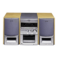
Do you have a question about the Aiwa XS-V30 and is the answer not in the manual?

Aiwa XS-V30 Specifications

General IconGeneral
TunerFM/AM
CD PlayerYes
BluetoothNo
USB PortNo
Remote ControlYes
Speaker Configuration2-Way
Tape DeckYes (Double Cassette Deck)

Summary

Product Identification

System and Mechanism Overview

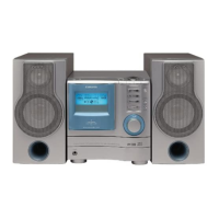
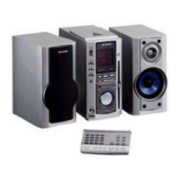
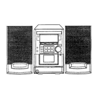
Identifies the system and its core tape and CD mechanisms.

System Specifications

Main Unit CX-GV30 Specifications

Detailed specifications for the main CX-GV30 unit.

Speaker System SX-G3 Specifications

Detailed specifications for the SX-G3 speaker system.

Cassette Deck Specifications

Specifications for the cassette deck section.

Disc Player Specifications

Specifications for the disc player section.

Laser Safety Precautions

Eye Protection During Servicing

Instructions to protect eyes from laser beam exposure during servicing.

Optical Block Replacement Precautions

Precautions for handling and replacing the optical block.

Pre-Repair Procedures

Power Supply Capacitor Discharge

Procedure for safely discharging electrolytic capacitors before repair.

Microcomputer Verification

Checks to confirm microcomputer defectiveness before replacement.

Electrical Parts List

Wiring Diagrams

Main, Jack, Fan Wiring

Wiring diagram for main unit, jack, and fan connections.

Main Unit Schematic (Amp/Head)

Schematic diagram for the main unit's amplifier and head sections.

Main Unit Schematic (Tuner)

Schematic diagram for the main unit's tuner section.

Deck and Head Wiring

Wiring diagram for the deck and head components.

IC Block Diagrams

LCD Display Details

LCD Segment Wiring

Diagram showing the wiring for LCD segments.

LCD Common Wiring

Diagram showing the common wiring for the LCD display.

IC Pinout and Description

LC877264V-5Y59 IC Pin Details

Detailed description of the LC877264V-5Y59 IC pin functions.

Service Adjustments

Tuner Section Adjustments

Procedures for tuning and tracking adjustments in the tuner section.

Deck Section Adjustments

Procedures for tape speed, azimuth, and response adjustments in the deck section.

Front Section Adjustments

Adjustment procedure for the clock in the front section.

CD Test Mode Operations

Starting and Exiting Test Mode

Instructions on how to start and exit the CD test mode.

CD Test Mode Functions

Description of functions and checking items within the CD test mode.

Automatic Adjustment Result Display

Displaying Focus Adjustment Results

How to display focus offset cancel and gain adjustment results.

Displaying Tracking Adjustment Results

How to display tracking offset cancel, balance, and gain results.

Mechanical Exploded Views

Mechanical Parts List

Tape Mechanism Parts List

Speaker Disassembly Instructions

Speaker Panel Removal

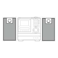
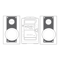
Step-by-step guide to remove the speaker front panel.

Speaker Panel Attachment

Instructions for attaching the speaker front panel.

Speaker Parts List

Accessories and Package List

Related product manuals