4
I/O Connections
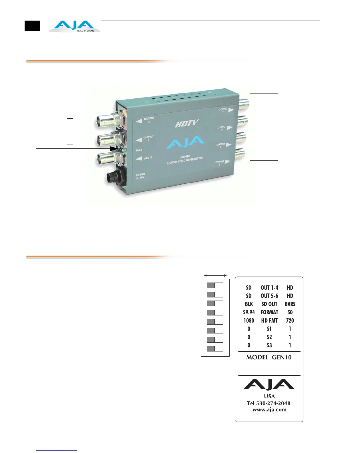
GEN10, Side View
User Controls
The user interface for the GEN10 is an
8-switch DIP accessible through a cut-
out in the bottom of the unit. Use the
DIP switches to configure outputs and
formats.
Note:
The combination of switch
settings determines the overall operation
of the GEN10.
The exact purpose of each DIP switch
and what it controls is described on the
following pages.
Configuration is
Determined by
DIP switch on
other side of
Converter
+ 5 to 18VDC
Power
Input
2nd
Power LED: When Green, this LED indicates
the GEN10 is powered up.
Output Group
Output 5
Output 6
AES 11
Output
Output 1
Output 2
Output 3
Output 4
1st
Output Group
Either Output Group can be set to SD or HD
1 2 3 4 5 6 7 8
DIP Switch Setting
LEFT RIGHT