EasyManua.ls Logo

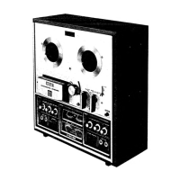
Akai 1730-SS

Akai 1730-SS
28 pages
To Next Page IconTo Next Page
To Previous Page IconTo Previous Page
Loading...
LINE
OUT
Fig.
3
RIO74.7K
tw
C107
10/16
C213
10/16
a
LINE
OUT
8
bs
—_
iC-201
ES
LD-314I
'
Cc
ian
10/725
9
8
t
ic-liol
=
&
My
LD-3141
|
Fz
REC
LEVEL
1ORA
CONTROL
y.
7,
MONITOR
SW2
Fig.
4
3.
ADJUSTMENT
OF
LINE
OUTPUT
LEVEL
1.
Playback
(See
Fig.
3)
Tape
2.
Recording
and
Playback
(See
Fig.
4)
a.
Set
the
Source/Tape
Monitor
Switch
to
“TAPE”
a.
Connect
V.T.V.M.
to
the
Line
Output
Jack.
position.
b.
Set the
Source/Tape
Monitor
Switch
to
b.
Connect
a
V.T.V.M.
(use
one
with
Milli-Volt
“SOURCE”
position.
scale)
to
the
Line
Output
Jack.
c.
Load
a
Scotch-150
blank
tape
and
set
the
c.
Playback
a
test
tape
(250
Hz
“0”
VU
recorded)
Record/Playback
Knob
to
recording
position.
at
7-1/2
ips.
tape
speed
and
turn
the
volume
d.
Feed
in
a
1,000
Hz
sine
wave
signal
from
an
VR-201
(10
KB)
until
the
Line
Output
level
Audio
Frequency
Oscillator
to
the
Line
Input
reaches
“0”
VU
1.228
V
(+4
dB).
of
the
1730-SS
and
turn
the
Recording
Level
Volume
Control
VR1
to
4
(10
KA)
unti
the
Line
Output
Level
reaches
“O”
VU
1.228
V
(+4
dB).
e.
Set
the
Source/Tape
Monitor
Switck
to
“TAPE”
position
and
turn
the
Recording
level
Volume
Control
VR1
to
4
(10
KA)
again
antil
the
Line
Output
Level
reaches
“O”
VU.
f.
Set
the
Source/Tape
Monitor
Switch
to
“SOURCE”
position
again
and
turn
the
Volume
Control
VR-101
(2
KB)
until
the
Line
Output
Level
reaches
“0”
VU.
g.
Repeat
twice
in
the
same
way
as
indicaticl
in
items
e.
and
f.
above.

Other manuals for Akai 1730-SS

Related product manuals