Do you have a question about the Akai AA-1010 and is the answer not in the manual?
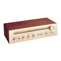
| Brand | Akai |
|---|---|
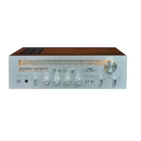
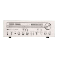
| Model | AA-1010 |
| Category | Stereo Receiver |
| Language | English |
Detailed performance specifications for power and pre-amplifier sections, including output and sensitivity.
Performance details for FM and AM tuner sections, including frequency range and selectivity.
Detailed steps and parameters for adjusting the FM tuner section.
Instructions for setting the idling current for the main amplifier channels.
Overall connection diagram of the entire system.
Detailed schematic for the MFC (Multi Function Circuit) board.