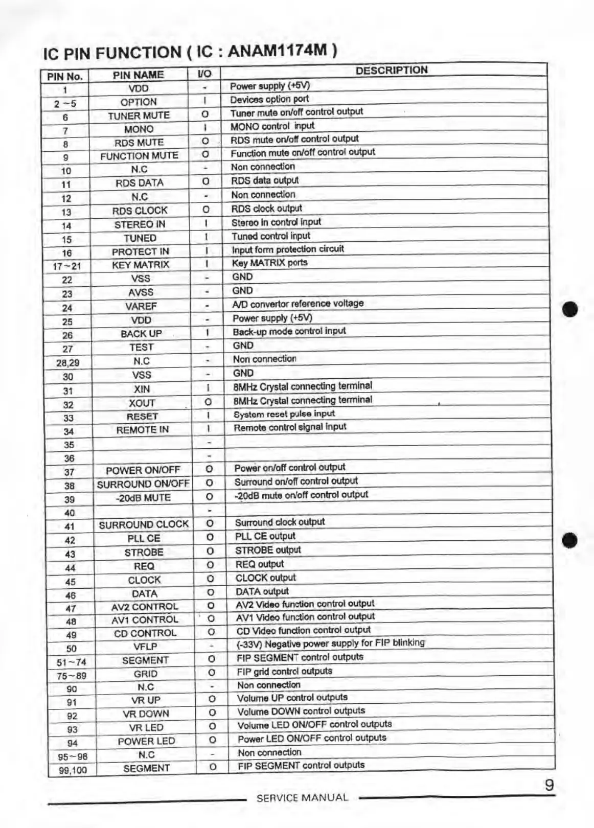
IC
PIN FUNCTION
(IC:
ANAM1174M)
PIN No.
PIN
NAME
uo
DESCRIPTION
1
voo
. Power supply
{-+5V)
2 - 5
OPTION
I
Devices option port
6
TUNER
MUTE
0
Tuner mute on/off control output
7
MONO
I
MONO control
input
8
RDS
MUTE
0
RDS mute on/off control output
9
FUNCTION
MUTE
0
Function
mute
on/off control
output
10
N.C
.
Non connection
11
ROS
DATA
0
RDS data outp\Jt
12
N.C
.
Non connection
13
RDS CLOCK
0
RDS clock output
14
STEREO IN
I
Stereo
in
contrd
Input
15
TUNED
I
Tuned control
Input
16
PROTECT IN
I
Input
fom,
protection circuit
17-21
KEY
MATRIX
I
Key
MA
TRIX ports
22
vss
.
GNO
23
AVSS
.
GNO
24
VAREF
. A/0 convertor reference voltage
25
voo
. Power supply ( +5V)
•
26
BACKUP
I
Back-up
mode
control
Input
27
TEST
.
GND
28.29
N.C
.
Non connection
30
vss
.
GNO
31
XIN
I
8MHz Crystal
connecting tem,lnal
32
XOUT
0
8MHz Crystal connecting temiinal
33
RESET
I
System rcoet pulse
input
34
REMOTE
IN
I
Remote control signal Input
35
.
36
.
37
POWER
ON/OFF
0
Power on/off control
output
38
SURROUND ON/OFF
0
Surround on/off control
output
39
-20dB
MUTE
0
-20dB mute on/off control
output
40
.
41
SURROUND CLOCK
0
Su1TOund
clock output
42
PLLCE
0
PLL
CE output
43
STROBE
0
STROBE output
•
44
REQ
0
REQ output
45
CLOCK
0
CLOCK output
46
DATA
0
DATA
output
47
AV2CONTROL
0
A
V2
Video function control
output
48
AV1 CONTROL
0
AV1 Video furr.tion control
output
49
CO CONTROL
0
CO Video function control output
50
VFLP
. {-33V)
Negative
power
supply
for
FIP
blinking
51
-
74
SEGMENT
0
FIP SEGMENT control outputs
75
-
89
GRID
0
FIP grid contrcl outputs
90
N.C
.
Non connection
91
VRUP
0
Volume
UP
ccntrol outputs
92
VROOWN
0
Volume DOWN control outputs
93
VRLED
0
Volume LED ON/OFF control outputs
94
POWER
LEO
0
Power LED ON/OFF control outputs
95-
98
N.C
-
Non connection
99,100
SEGMENT
0
FIP SEGMENT control outputs
9
SERVICE
MANUA
L