EasyManua.ls Logo

Akai ADVANCE61 User Manual

Akai ADVANCE61
61 pages
To Next Page IconTo Next Page
Page #1 background imageLoading...
Page #1 background image
SPECIFICATIONS
Technical Specification
Technical SpecificationTechnical Specification
Technical Specification
Keyboard
61 velocity- and pressure-sensitive keys
10-octave range with Octave Down/Up buttons
Pitch-bend wheel
Modulation wheel
Encoders
8 360° assignable encoders
1 360° encoder with push function for display navigation
Pads
8 velocity- and pressure-sensitive pads; multicolor-backlit
Switches
8 assignable switches; amber-backlit
23 function switches; amber-backlit
4 directional cursor buttons
Display
3.75" x 2.125" (95.3 mm x 54 mm) full-color LCD
Connections
1 1/4" (6.35 mm) TRS expression pedal input
1 1/4" (6.35 mm) TS sustain pedal input
1 5-pin MIDI input
1 5-pin MIDI output
1 USB port
1 power adapter input
Power
6 V DC, 1 A, center-positive
Dimensions
(width x depth x height)
36.0" x 11.5" x 3.5"
91.4 cm x 29.2 cm x 8.9 cm
Weight
12.1 lbs.
5.5 kg
SERVICE MANUAL
MODEL:ADVANCE61
Question and Answer IconNeed help?

Do you have a question about the Akai ADVANCE61 and is the answer not in the manual?

Akai ADVANCE61 Specifications

General IconGeneral
BrandAkai
ModelADVANCE61
CategoryRecording Equipment
LanguageEnglish

Summary

Product Specifications

Key Component Specifications

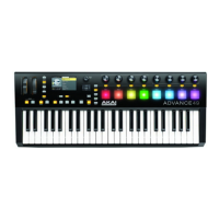
Details on keyboard, encoders, pads, switches, display, connections, power, dimensions, and weight.

Disassembly Procedures

Cabinet and Top Panel Disassembly

Steps for removing the outer casing.

Rear I/O PCB Assembly Disassembly

Procedure for removing the rear input/output board.

Top Right PCB Assembly Disassembly

Steps for removing the right-side circuit board.

Main PCB Assembly Disassembly

Procedure for accessing and removing the main circuit board.

Top Left PCB Assembly Disassembly

Steps for removing the left-side circuit board.

Pitch/Mod LED PCB Assembly Disassembly

Procedure for removing the pitch/modulation LED board.

P/M Wheel Assembly Disassembly

Steps for removing the pitch/modulation wheel assembly.

Wiring Diagram

System Wiring Overview

Illustration of electrical connections between components.

Packing Diagrams

US Packing Diagram

Details on how the product is packaged for the US market.

AUS Packing Diagram

Details on how the product is packaged for the Australian market.

Explode Diagram

Component Assembly Overview

Visual guide showing component assembly order.

Bill of Materials

ADW3AKA01 Component List

Comprehensive list of all parts, quantities, and part numbers.

Testing Procedures

MIDI Jack Test

Steps to verify MIDI port functionality.

Screen and Pad Tests

Procedures for testing display color and pad color accuracy.

Keybed and Switch Tests

Procedures for testing keybed, aftertouch, and switches.

Wheel and Encoder Tests

Procedures for testing pitch/mod wheels and rotary encoders.

Pedal and Pad Functionality Tests

Procedures for testing sustain/expression pedals and pads.

Circuit Diagrams

Top Level Schematic

Overall system circuit diagram.

Keybed Interface Schematic

Circuit for reading key presses and matrix scanning.

MIDI Analog Schematic

Circuitry for MIDI ports and analog signal processing.

USB Power Management Schematic

Circuit for handling USB power input and regulation.

ADW1 Wheel LED PCB Schematic

Circuit for LED control on the wheel assembly.

Top Right Pads/Pots Schematic

Circuit for pads and potentiometers on the right side.

Top Right LED Switch Schematic

Circuit for LEDs and switches on the right side.

Related product manuals